Facebook
 Google
 GitHub
 Linkedin
Lestraveled
- Joined May 19, 2014
- 1,946
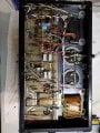
I am in this camp....................Since transformers were changed that is the area I would suspect..........
- Do the schematics show an electrostatic shield in the power transformer??.............I emailed the company and was told that they don't have the schematic available for this amp, but they did send me some schematics of their equivalent connections, basically a schematic showing the topology that applies to all of their early amps..............
- Do the power transformers in your amps have an electrostatic shield??