Need help please with a Voltage alarm with LT1017

ebeowulf17

Joined Aug 12, 2014
3,307
That is brilliant. So basically the feedback resistors with 300k and 1k are new plus the capacitors C1-C3. My R2 is currently 1K, so this should make no big difference. Just a more stabile zener diode operation as far as i understand it, correct?
How do you calculate the reefback resistors please? is there a "standard formular" ?
Thanks a lot for your help. Will build it later today :)
Pages 15 & 16 of the Microchip MCP6542 datasheet do a good job of explaining hysteresis for both inverting and non-inverting inputs.

http://ww1.microchip.com/downloads/en/devicedoc/21696f.pdf

I always go back to this datasheet because it's from the first op amp circuit I ever designed, I had absolutely no idea what I was doing, and this datasheet taught me everything I needed. To be honest, the great datasheet was 99% of the reason that we used that part instead of some other op amp or comparator. I really love good datasheets (and app notes!)
 

Bordodynov

Joined May 20, 2015
3,428
I used instead of the Zener diode a chip with three conclusions in the simplest inclusion. This will greatly increase the stability of the reference voltage (2.5V) with respect to temperature and supply voltage (You can also use 1 kOhm). Read the datasheet. The hysteresis width is approximately equal to PPvOut * R1 / (R1 + R5) ~ 14V / 300 = 46mV.
 

Thread Starter

dscha

Joined Nov 19, 2018
13
Hi Bordodynov,

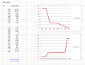
Thanks a lot for your work, much appreciated. Followed your circuit, only still have the zener diode as reference. 0.1u are directly soldered to the power pins of the LT1017 and I have the hysteresis (see table and chart), but i also still have this "limbo state" around 3V. I don't know if it is oscillating or a stable voltage, don't have a oscilloscope at my disposal at the moment. But the idea of the feedback loop would have been to not to have this floating area.
Sorry to bother you any longer, but any more ideas/suggestions?
Thanks
D
Screen Shot 2018-11-20 at 22.00.46.png
 

Thread Starter

dscha

Joined Nov 19, 2018
13
It seems that the feedback loop does not have any influence on this behaviour. It seems that there is a window where the IC goes to 3.X volt in between the states. BTW: I tried a LM393. They are pin compatible. Sames setup, same behaviour, but the "limbo voltage" was around 5 Volt.

I am a little confused now. I always thought that a comparator or op-amp used as comparator switches between two states and not something in between. Apparently that is not the case.

Any thoughts are very welcome.

thanks
D
 

ebeowulf17

Joined Aug 12, 2014
3,307
It seems that the feedback loop does not have any influence on this behaviour. It seems that there is a window where the IC goes to 3.X volt in between the states. BTW: I tried a LM393. They are pin compatible. Sames setup, same behaviour, but the "limbo voltage" was around 5 Volt.

I am a little confused now. I always thought that a comparator or op-amp used as comparator switches between two states and not something in between. Apparently that is not the case.

Any thoughts are very welcome.

thanks
D
I have a really hard time believing your circuit is putting out a solid signal around 3 or 3.5VDC, unless there's a wiring error. It's got to be oscillating.

Lacking a better explanation, my first inclination would be add more hysteresis and see if the problem is reduced, although your undefined region is rather large. Maybe replace the 300k with ~30k. It wouldn't necessarily be the final solution, but it might help us understand what's going on if it works.

Another approach would be to reduce noise on the input signal. Small-ish caps to ground on each input would form simple RC filters in conjunction with the existing input resistors. Maybe try 0.1uF - 1uF. Those values are wild guesses, since have no idea what the nature, or magnitude, of any noise would be.
 

Bordodynov

Joined May 20, 2015
3,428
If you have a multimeter, then switch it to AC voltage mode. And measure the alternating voltage at the output of the comparator.
And I agree with the need for filtering, perhaps the whole system is generated due to feedback on the resistance of the power supply. Put a ~ 0.1-1uF capacitor on the inverting input. It is advisable not to use an electrolytic capacitor (due to leaks)
 

AlbertHall

Joined Jun 4, 2014
12,636
The frequency of any oscillation may well be outside the range of a multimeter and you would need to check that the meter on AC ranges does not indicate with only DC input - some do.
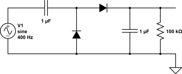
You could make the circuit below to check for oscillation. Use 100nF for the capacitors and small signal diodes like 1N4148. Connect the input to the circuit to the output of the LT1017. With your circuit somewhere on that plateau, if you measure any DC voltage on the output of this circuit then there is some oscillation.
 

Thread Starter

dscha

Joined Nov 19, 2018
13
Hello again,

thanks again for your input. I am learning a lot! BTW: the entire circuit is currently on a bread board, so that might also make it more unstable. I might rebuild it on a little experimental PCB. I also got hold of an oscilloscope (very interesting item here http://expeyes.in. Price in UK about 60 quid). And yes, there are oscillations. The feedback resistor (300k) does not make a big difference as it seems and when Ii reduce it too much the hysteresis gets too large. But I am experimenting with the resistor values there as well.

What does make a difference is when I disconnect the transistor stage, so removing the load. The current that flows when the transistor switches on has an influence on the behaviour since higher current means higher voltage drop in the 1017 as far as i understand it. I decreased the current by increasing the Rb (relay and buzzer still working, still enough Ic to run the show) and it seems to be better. I will now work on your recommendations regarding the capacitors and will keep trying and keep you posted.

Thanks, your help is much appreciated!

best
Dietmar
 

Thread Starter

dscha

Joined Nov 19, 2018
13
Hello,
short update: I put ceramic capacitors to the non-inverting and the inverting input and now it is working almost perfectly. So it was the noise from the inputs! There is still a little jitter, but it is so minor since the relay is too slow.
best
D
 

MisterBill2

Joined Jan 23, 2018
27,730
Could it be oscillating? Maybe that's not a steady 3.5VDC output, but a high speed oscillation that averages out to around 3.5V as read by a meter.

If so, maybe you just need a feedback resistor to add some hysteresis. I didn't see any mention of hysteresis in the datasheet, so I'm not sure what, if any, is built into the device.
CERTAINLY most comparators will oscillate very well if they are given a chance. Thus in addition to assuring very good bypassing of the power leads a bit if positive feedback is a good idea, so as to work toward intrinsic stability. And the really good news is that oscillation has been a big problem long enough that a lot of solutions have been found and published. So help is available if that is the problem, and also if it isn't the problem.
 
Top