Hi,
I'm doing a Ultrasonic Mist Maker followed: https://www.instructables.com/DIY-MISTFOG-MAKER-USING-IC-555/
there are few questions:
1. is the 10 nf yellow capacitor same as the general ceramic capacitor?
2. I bought a package of mixed values inductance,from 6uh to 200uh, how to figure out them?
3. I made one board, the 10 ohm resistance burnt as soon as power on ? why? that connected to pin 3 and two ends of 5K Potentiometer then goes to the Gate of IRFZ44N.
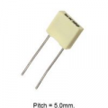
The 10nF (or 0.01uF as it's more commonly refenced) _box capacitor_ (polyester film), non-polarized usually has a marking on the top end. What is the marking on the end (like this):
Really, the first step should be seeing if that 555 circuit is producing a signal. It is hard to see the difference between zero and nothing. So the first step is with the scope input common connected to the power supply negative, along with the circuit, connect the scope signal input to pin 3 of that 555 IC. Not only will that verify if the circuit is working, it will also allow setting the scope vertical gain, which is sort of important..I don''t recall any mention that the circuit was working as intended, or even working at all. After that, checking what signal is on the gate of the FET, and then the drain terminal will tell us a whole lot.
The 10nF (or 0.01uF as it's more commonly refenced) _box capacitor_ (polyester film), non-polarized usually has a marking on the top end. What is the marking on the end (like this):
Really, the first step should be seeing if that 555 circuit is producing a signal. It is hard to see the difference between zero and nothing. So the first step is with the scope input common connected to the power supply negative, along with the circuit, connect the scope signal input to pin 3 of that 555 IC. Not only will that verify if the circuit is working, it will also allow setting the scope vertical gain, which is sort of important..I don''t recall any mention that the circuit was working as intended, or even working at all. After that, checking what signal is on the gate of the FET, and then the drain terminal will tell us a whole lot.
I just watched that video and what is interesting is that we never see the connections on the bottom of the circuit board, nor do we see the battery pack again when the thing is working. There could easily be a separate device connected to those red and black wires, and the two terminal strips could be wired straight across, so that none of the parts on that board are involved.
Does your toroid inductor look like the one in the pictures?
I just watched that video and what is interesting is that we never see the connections on the bottom of the circuit board, nor do we see the battery pack again when the thing is working. There could easily be a separate device connected to those red and black wires, and the two terminal strips could be wired straight across, so that none of the parts on that board are involved.
Does your toroid inductor look like the one in the pictures?
Thanks.
I used two types of inductor as picture attached. I watched few of the Youtubes, and the circuit all similar, and my last one did shown some wave mentioned on #26.
The first circuit uses a 10nF timing capacitor and the second circuit uses a 1nF. Both circuits are from India.
The second circuit shows horrible soldering by carrying the solder to the joint on the soldering iron and the solder seems to be 60/40 and not 63/37 since the solder joints move and take time to solidify.
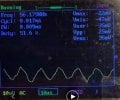
Your scope shows a very low signal level.
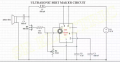
What are the numbers on your timing capacitor C2 (on the last schematic)?
The first circuit uses a 10nF timing capacitor and the second circuit uses a 1nF. Both circuits are from India.
The second circuit shows horrible soldering by carrying the solder to the joint on the soldering iron and the solder seems to be 60/40 and not 63/37 since the solder joints move and take time to solidify.
Your scope shows a very low signal level.
What are the numbers on your timing capacitor C2 (on the last schematic)?
Thanks.
C2 is 1 nf.
I checked the Pizeo from the seller web, they have some of that works on 1 - 8 KHz, and some of that works on 1.7 MHz, my type my be the latter, how can get that high frequency?
The soldering iron in that video was way too hot, and certainly in the condition that I would expect for an iron way too hot. And did anybody else see that there was never any connecting of the parts shown and never a view of the connection side of that assembly. Thus the whole thing could be a fake. Once again, that is part of why I call it the cartoon channel.
It is possible to determine the resonant frequency for one of those piezo disks by driving it with an oscillator thru a resistor and observing the frequency with the voltage peak.
The soldering iron in that video was way too hot, and certainly in the condition that I would expect for an iron way too hot. And did anybody else see that there was never any connecting of the parts shown and never a view of the connection side of that assembly. Thus the whole thing could be a fake. Once again, that is part of why I call it the cartoon channel.
It is possible to determine the resonant frequency for one of those piezo disks by driving it with an oscillator thru a resistor and observing the frequency with the voltage peak.
Thanks.
I can try that.
But I tend to that pizeo. I bought are working at 1.7 MHz, thing is how to get that high frequency on 555.
can I try this one, does it need exactly same 1.7?
BTW. I didn't use iron yet, I just use breadboard now.
1.7MHz is a radio signal. I am surprised to see your messy wiring on a breadboard can produce an oscillating frequency so high.
The IRFZ44 needs a gate-source signal of 10V for it to fully turn on. Yours is only 7V which will be less when driving the high capacitance of the Mosfet gate-source. An IRLZ44 will work much better with your 555 output level.
At that frequency it seems that the 555 is a poor choice, and that an actual oscillator circuit using the piezo element as the frequency determining component would assure that the drive was in resonance. Especially with such a simple variable resistor it will be very challenging to set it at the disk resonance point. And an RC timing circuit is fairly temperature sensitive.
And now the big question is what is the purpose of this exercise, anyway? IS there an intended application for this? or is it just an experiment because it seems like fun?
1.7MHz is a radio signal. I am surprised to see your messy wiring on a breadboard can produce an oscillating frequency so high.
The IRFZ44 needs a gate-source signal of 10V for it to fully turn on. Yours is only 7V which will be less when driving the high capacitance of the Mosfet gate-source. An IRLZ44 will work much better with your 555 output level.
At that frequency it seems that the 555 is a poor choice, and that an actual oscillator circuit using the piezo element as the frequency determining component would assure that the drive was in resonance. Especially with such a simple variable resistor it will be very challenging to set it at the disk resonance point. And an RC timing circuit is fairly temperature sensitive.
And now the big question is what is the purpose of this exercise, anyway? IS there an intended application for this? or is it just an experiment because it seems like fun?
with that waveform there are a whole lot of harmonics and probably it will interfere with quite a few things, and be in violation of FCC rules if it is in the US.
with that waveform there are a whole lot of harmonics and probably it will interfere with quite a few things, and be in violation of FCC rules if it is in the US.
I think the intermittent contacts, rows of contacts and messy long wires on the solderless breadboard prevent the circuit from working properly at the very high frequency for a 555. Maybe another 555 or from a different manufacturer would work better.

 Facebook
 Google
 GitHub
 Linkedin