Facebook
 Google
 GitHub
 Linkedin
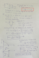
Ok I will rework, but only thing I wanted to say is that since i already calculate "t" in the initial posts, was not trying to calculate "t", but wanted to calculate the circuit voltages and currents after the switch is opened. The initial inductor current i think i made a mistake by assuming t=1 sec, i have used that value to simplify the calculations.
Need Help in LC and diode circuit
- Thread starter Vihaan@123
- Start date