 Facebook
 Google
 GitHub
 Linkedin
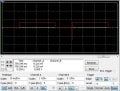
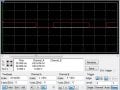
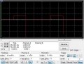
The circuit connection is alright. The transformer used here is 12-0-12 to 230 volts transformer. Here we have used 25 to 1 but don't worry. In practical we have used 12 to 230 transformer. But the problem is I am not getting the required output. Maybe we are making wrong at a simple point but can't identify. Please help me, guys. I am stuck here for many days.The output of the 555 timer is a square wave. The waves of the bases of transistor BC547, Power transistor 2N6292 s are also given in the attachment respectively. There are spikes that are coming from bc547 and the lower power transistor 2n6292(Q3). If you gen any faulty then please let me know.
Thankyou
Thankyou
Attachments
-
 99.8 KB Views: 29
 -
 60.4 KB Views: 23
 -
 57.8 KB Views: 23
 -
 57.8 KB Views: 22
 -
 56.7 KB Views: 22


