Need Help in Designing a Full Wave Bridge Rectifier

Thread Starter

MarsG

Joined Sep 12, 2015
24
Im new to circuits, so bear with me lol.
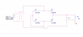
My homework assignment is to design a Full Wave Bridge Rectifier (Attached the circuit I built in pspice and the full description of the assignment below.) The rectifier is to have a filter Capacitor across the Load.
Given:
Input = 120v-rms, 60Hz
Load = 155 Ohms
Voltage Across individual diodes = .7V (1.4 together)


The Avg Outpt Voltage is to be 15v with a ripple of +- 1V peak

I have to determine the Outpt Voltage, the peak to peak ripple voltage and the Avg/Max diode currents.

120V-rms = 170v pk (Vrms= Vpk/sqrt2)

with the voltage drop from the diodes (1.4v)
(120-1.4)sqrt2=Vpk=168Vpk

The ripple frequency is double the source
60Hz----> 120Hz

Vripple = Iload/fC

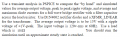
The problem im having is that I do not know the value of the capacitor to use nor the Load current, and im not sure how to incorporate the transformer. (was told to use 1Henry for the L1 Value not sure about L2)
 

Attachments

WBahn

Joined Mar 31, 2012
29,976
By L1 and L2, I'm assuming you are talking about the input and output sides of the transformer. You can probably assume that the ratio will be the same as the square of the turns ratio. That will be the primary way of setting the average voltage. The capacitor will set the ripple voltage.

If the average voltage across the load is to be 15 V and the load resistance is 155 Ω, what more do you need in order to at least get a good estimate of the average load current?
 

Thread Starter

MarsG

Joined Sep 12, 2015
24
By L1 and L2, I'm assuming you are talking about the input and output sides of the transformer. You can probably assume that the ratio will be the same as the square of the turns ratio. That will be the primary way of setting the average voltage. The capacitor will set the ripple voltage.

If the average voltage across the load is to be 15 V and the load resistance is 155 Ω, what more do you need in order to at least get a good estimate of the average load current?
My primary concern is the transformer, we haven't really covered transformers yet so im not sure on how to determine the turns ratio or step down voltage. Dint really make my way down to the load because of the fact im stuck at the transformer but yea I could use ohms law on the load.
 

WBahn

Joined Mar 31, 2012
29,976
When you head out on a trip somewhere, do you just start driving in some random direction and because you haven't made your way down to figuring out where you are trying to end up?

When you design a circuit you start from what you want to achieve. What you want to achieve is a particular voltage specification at the load, so you start your design at the load. From that you figure out what the voltage is you need at the input to bridge circuit, which is also the output of the transformer. If you know what you need at the output of the transformer and you know what you have at the input of the transformer, figuring out the turns ratio should be fairly straightforward.
 

Thread Starter

MarsG

Joined Sep 12, 2015
24
My primary concern is the transformer, we haven't really covered transformers yet so im not sure on how to determine the turns ratio or step down voltage. Dint really make my way down to the load because of the fact im stuck at the transformer but yea I could use ohms on the load.
When you head out on a trip somewhere, do you just start driving in some random direction and because you haven't made your way down to figuring out where you are trying to end up?

When you design a circuit you start from what you want to achieve. What you want to achieve is a particular voltage specification at the load, so you start your design at the load. From that you figure out what the voltage is you need at the input to bridge circuit, which is also the output of the transformer. If you know what you need at the output of the transformer and you know what you have at the input of the transformer, figuring out the turns ratio should be fairly straightforward.
I understand now, because I have 170V(120V-rms) going into the transformer and I need about 17V(12V-rms) to compensate for the diode voltage drops, the ratio would then be 170:17 and L1 being 1 Henry would make L2 0.1 Henry.
Thank you for the explanation and your time.
 
Top