 Facebook
 Google
 GitHub
 Linkedin
Photos attached.
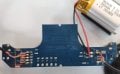
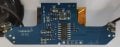
This is part of the case circuitry of a bluetooth earphone set.
Unfortunately the case no longer charges the earpieces, see video: https://www.mediafire.com/folder/n4nfj3j2qpdyg/pamu+not+charging+case
The main part I am interested in is the B98̅4 (tried to put the combing overline only over 8, ain`t working that good):

I managed to find many many sot23-6 components (boost / step-up converters suitable for battery operation - e.g. very low quiescent current) but unfortunately none matches the pinout on the board...
I would also be interested to find the other parts on the board, it seems that there is no more led display of the case battery, although it does charge its 902030 (size) lithium battery when I connect the microusb. The led display is surely controlled by the (ST Micro) STC 15w404as cpu which might also be dead (but I don`t really care about it).

The 57b4 might be some version of tp4057 but I`m not sure what the YJ32 SOT23-5 is....
I had attached pictures with the entire circuit and closeups with all the parts in detail.
Thank you in advance!
This is part of the case circuitry of a bluetooth earphone set.
Unfortunately the case no longer charges the earpieces, see video: https://www.mediafire.com/folder/n4nfj3j2qpdyg/pamu+not+charging+case
The main part I am interested in is the B98̅4 (tried to put the combing overline only over 8, ain`t working that good):
I managed to find many many sot23-6 components (boost / step-up converters suitable for battery operation - e.g. very low quiescent current) but unfortunately none matches the pinout on the board...
I would also be interested to find the other parts on the board, it seems that there is no more led display of the case battery, although it does charge its 902030 (size) lithium battery when I connect the microusb. The led display is surely controlled by the (ST Micro) STC 15w404as cpu which might also be dead (but I don`t really care about it).
The 57b4 might be some version of tp4057 but I`m not sure what the YJ32 SOT23-5 is....
I had attached pictures with the entire circuit and closeups with all the parts in detail.
Thank you in advance!
Attachments
-
 112.7 KB Views: 4
 -
 32.8 KB Views: 4
.jpg")


