Facebook
 Google
 GitHub
 Linkedin
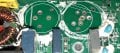
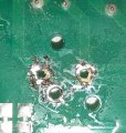
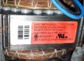
I need help finding 2 of these capacitors for a G.E. washer. They were on the circuit board attached to the motor. It is a 3-pin cap, which is making it very difficult to find. Here are some pics of the cap and the motor tag. Thanks!
Attachments
-
 1.3 MB Views: 18
 -
 2 MB Views: 19
 -
 245.3 KB Views: 19