Need help designing a latching circuit

Thread Starter

cgw94

Joined Jun 11, 2020
42
I am working on a project that I am 90% done with. I just need to add one last feature.

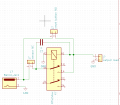
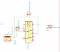
I am designing a simple flood detection circuit. Here is the flow right now.

Power on - arm the device - start checking for floods - if flood detected, you must rearm with a push button. Can not rearm while flood is still detected.

The change i need to make is that I need the device to start up without needing to be armed. My problem right now is that I am treating a "flood" and loss of power as the same thing.

The circuit works like this:

On power on, the circuit is open until i press the button. The relay then latches until a flood breaks the contact again. The circuit "resets" when the button is pushed.

I have a DPDT just in case i need the a different power source to control


A few notes:

1. They do sell a Normally Open version of the sensor but id rather not have to buy more.
2. I know i can use an Arduino to do this pretty easily but I want the challenge of doing it solely with circuitry.
3. Adding more relays is not a problem if that would make it easy.
4. The circuit works, I have no issues with the current function, just want to modify to add the feature described.

TLDR: I want to adjust this circuit such that it does not need the button to be pushed on power up to activate the circuit, instead, I want the button to only to be used after a flood is detected in order to reset the circuit. I do not want the circuit to be able to restart on its own after a flood is detected (Sensor Opens.)

Thanks! Hope some of you find this interesting!
 

Attachments

ElectricSpidey

Joined Dec 2, 2017
2,758
A small relay with a capacitor in series with the coil can press a button for you on powerup.

Also you need to place a high value resistor across the capacitor to discharge it, the value must be high enough as to not prevent the relay from dropping out.
 
Last edited:

Thread Starter

cgw94

Joined Jun 11, 2020
42
A small relay with a capacitor in series with the coil can press a button for you on powerup.
That is very interesting. I am not sure how that would look exactly. So a separate relay with a capacitor. Would the capacitor latch the second relay after it charges? And during that "charge time" that would be my button being pressed. Then while the circuit is on that button stays "pressed"?
 

Thread Starter

cgw94

Joined Jun 11, 2020
42
What relay are you using?
What is the relay coil voltage and current?
Sorry about that! forgot about that stuff. It is a 12v supply energizing a 12v relay that powers a 12v load. The current rating of the relay is 12A NC and 20A NO. My load draws about 2A.

The relay i am using is an older DIN mount Omron relay.
 

Thread Starter

cgw94

Joined Jun 11, 2020
42
You could likely use a capacitor to activate that relay upon power-up without needing a second relay, but I need to know the relay coil resistance.
Here is the data sheet, amperage is lower that i thought.

http://www.ia.omron.com/products/family/1731/lineup.html

I am using the G2R-2-S(S) with the P2RF-08-PU socket

coil resitance 1,113 Ω
 

Thread Starter

cgw94

Joined Jun 11, 2020
42
Ok here is the updated circuit. I added the capacitor in this way so that it is only charged when there is no flood detected.

@ElectricSpidey The 2 amp load is more of a 2 amp peak spike current. normal operation is closer to 600mA. (Actually the reset button helps prevent large spikes). Would the coil resistance be large enough to discharge the cap?

@crutschow Im guessing the resistance of the coil will impact my cap size?

This is really helping guys thanks! If i can just pop a capacitor in there i'll be delighted!

(EDIT) I moved the capacitor to connect directly to the supply because i dont care about flooding for this function.

I am a little worried the capacitor wont charge in this setup...
 

Attachments

Last edited:

crutschow

Joined Mar 14, 2008
34,285
coil resitance 1,113 Ω
That corresponds to the 24Vdc coil.
The 12Vdc coil resistance is 278 ohms.
Might need a pretty big cap, considering the 2 amp load in parallel with the relay coil.
Yes.
You would need to connect the load through the other contacts to isolate the load.
LTspice simulation below:
R2 is to protect the contacts from the surge current due to C1.

The relay output latches (blue trace) when the power is applied (green trace).
The relay opens when the Sensor opens (red trace).
The relay is again closed when the reset is pushed (yellow trace).

1600444327446.png
 

Thread Starter

cgw94

Joined Jun 11, 2020
42
That corresponds to the 24Vdc coil.
The 12Vdc coil resistance is 278 ohms.
Yes.
You would need to connect the load through the other contacts to isolate the load.
LTspice simulation below:
R2 is to protect the contacts from the surge current due to C1.

The relay output latches (blue trace) when the power is applied (green trace).
The relay opens when the Sensor opens (red trace).
The relay is again closed when the reset is pushed (yellow trace).

View attachment 217527
THIS IS GREAT!!! I've never tried my hand at LTspice. looks pretty cool!

I have a few questions just so i can apply this in the future if need be. The cap size is based on the coil resistance? If the charge time is too fast (eg. the relay doesn't activate) i should increase cap size? (I just remembered the sensor is technically powered as well, this may impact my charge timing as well).
R2 run to the open switch, this is for when i close the switch. When doing so, this will cause the cap to discharge? not quite following that part.

Thank you so much again! I am going to play around with this on a smaller 5V breadboard circuit for a while so i can understand it better! Love learning new tricks like this!
 

KMoffett

Joined Dec 19, 2007
2,918
This was my water level alarm silence circuit. I think it will meet all you requirements. Alarm is active once power is applied, no need activate with a switch. Once water is detected a pulse triggers the SCR. Pushing the button shorts out the SCR, shutting it off. Circuit will again become active as soon as the water is removed. No current drawn until the circuit alarms or only very little when silenced.

Alarm bypass-Flood.jpg
 
Last edited:

crutschow

Joined Mar 14, 2008
34,285
The cap size is based on the coil resistance?
Yes.
The capacitor has to be large enough to latch the relay (requires about 15ms) and that time is based upon the RC time-constant (where R is the relay coil resistance).
470μF is likely significantly larger than needed, but too large is no problem.
R2 run to the open switch, this is for when i close the switch. When doing so, this will cause the cap to discharge? not quite following that part.
Yes, the Reset switch will discharge the capacitor, which is just an inadvertent result of having the capacitor across the switch.
Discharging the capacitor is not necessarily required for the Reset switch to work.
 
Last edited:

Thread Starter

cgw94

Joined Jun 11, 2020
42
This was my water level alarm silence circuit. I think it will meet all you requirements. Alarm is active once power is applied, no need activate with a switch. Once water is detected a pulse triggers the SCR. Pushing the button shorts out the SCR, shutting it off. Circuit will again become active as soon as the water is removed. No current drawn until the circuit alarms or only very little when silenced.

View attachment 217531
I think this could work if i used a NO switch.
 

Thread Starter

cgw94

Joined Jun 11, 2020
42
Yes.
The capacitor has to be large enough to latch the relay (requires about 15ms) and that time is based upon the RC time-constant (where R is the relay coil resistance).
470μF is likely significantly larger than needed, but too large is no problem.
Yes, the Reset switch will discharge the capacitor. which is just an inadvertent result of having the capacitor across the switch.
Discharging the capacitor is not necessarily required for the Reset switch to work.
Ahhhh gotcha. One last question and I'll try and figure the rest out on my own. Does it need to be a electrolytic capacitor? The biggest one i have is 10uF but I know i have larger 0805 ceramic ones. (This circuit will eventually be a PCB so that would be handy for the future.) All i know about electrolytic's is that they have polarity and cant handle larger voltages. Would either work for this instance?

I am also not worried about increasing charge time. a few extra ms of water shouldn't hurt much.
 

crutschow

Joined Mar 14, 2008
34,285
Does it need to be a electrolytic capacitor? The biggest one i have is 10uF but I know i have larger 0805 ceramic ones
It doesn't need to be electrolytic, but non-electrolytic capacitors above 10uF are physically very large.
I doubt that you have ceramic caps larger than 10uF.
 

Thread Starter

cgw94

Joined Jun 11, 2020
42
It doesn't need to be electrolytic, but non-electrolytic capacitors above 10uF are physically very large.
I doubt that you have ceramic caps larger than 10uF.
Right again!, I was thinking nano not micro. Welp off to mouser for me!

Thanks again! Really appreciate it. Ill post the PCB layout here if it gets to that stage.
 

crutschow

Joined Mar 14, 2008
34,285
One thing I forgot.
The capacitor size is also determined by the rise-time of the power.
A slow rise will require a larger capacitor.
Do you know how fast the power voltage rises when turned on?
 
Top