Yes, DC bias is the same thing as a bias voltage generally. Most circuits have some required biasing conditions in order for them to operate properly. For example, a single transistor audio amplifier will often require some DC voltage levels to be established at the terminals of the transistor to put it in (or near) the active region of operation. The AC audio signal is then typically impressed on top of the DC voltage.
When there is a small AC voltage (say 100mVpp) riding on top of a larger DC voltage (like 1.5V DC), we say that the AC signal has a DC offset on it.
DC coupling simply means that the connection from one part of a circuit to another in a way that DC current can flow - i.e. it is Directly Coupled. This is opposed to AC coupling, where either a capacitor or transformer is used to couple to parts of a circuit together. With AC coupling, the AC portions of the signal (like the audio) is coupled from one part of a circuit to another, but the DC offset or DC bias is blocked. This is very common and useful because it allows each of the circuits to have their own required bias conditions, but still be connected together to allow an AC signal to flow between them.
You may want to check out this video which discusses AC and DC coupling as it refers to oscilloscope operation, but the principles discussed above are discussed.
1st, in regard to the attachment shown in that shows biasing, is my understanding of biasing correct, right? When bias by 2.5V what could be the amplitude of the signal if a signal of 5 V is applied to the input (it is going to be 7.5V, right)?
2nd, in regards to:
An op amp can not produce signals outside its power rails, so if it is only powered by a single ended supply, that is from 0V to a positive voltage, you need to bias (or shift) the signal up to a center point between the two supply voltages. Other op amp circuits are powered by a split supply, that is a supply that has three wires and give -V 0V and +V. This can have it's signal biased at zero volts as the output can swing either side of zero.
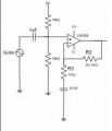
Does it mean for example: when the op amp is connected to +5 and -5V that I don't need biasing. But when the op amp is connected to +5V and ground I need biasing. Because sometimes I see op-amps that is connected to +5V and -5V is still biased by using resistors of equal resistances in voltage divider setup. For example the circuit attached. why?
Many components, such as transistors, operate in the DC region. You put them in the middle of the DC operating range, then use a capacitor to couple the AC into this mix. You also use a capacitor to pull the amplified AC out of this mix.
In this case your op amp is using one power supply, which mean it needs a bias. If it were using two power supplies (±) then it would handle AC directly.
Don't know if this is what you were asking, hope it helps.
Voltage biasing of a class A audio amplifier is the example most often cited, but it is by no means the whole story:
Not everything that is biased is an amplifier. Other things, like for instance diode demodulators, may require bias.
Not all amplifiers are audio amplifiers (radio-frequency, video, servo...)
Not all amplifiers are linear class A (class B, Class C...)
Bias current may be as relevant as bias voltage.
Biasing generically refers to the principle of establishing a quiescent working point for an electronic device, often but not always an amplifying device such as a transistor, so that it is ready to respond to signals appropriately, linearly or otherwise as the particular application requires
The working point may be defined in terms of voltages and currents. Signal excursions occur with reference to the working point
A DC offset is a difference between some DC quantity, and the quantity as responded to by a device. Often, but not always, this is an internal error voltage, due for instance to manufacturing variability in a differential amplifier or comparator. Sometimes deliberate offsets are added to a signal, for instance to bring it within the input range of a DC amplifier.
DC coupling means connecting together amplifiers or other circuits in such a way that DC signal level changes propagate through the system, as opposed to AC coupling, where only AC variations are transferred. The latter typically uses capacitors, or less often transformers or other inductors, which block the passage of the DC levels but allow the AC to pass through.
...Does it mean for example: when the op amp is connected to +5 and -5V that I don't need biasing. But when the op amp is connected to +5V and ground I need biasing. Because sometimes I see op-amps that is connected to +5V and -5V is still biased by using resistors of equal resistances in voltage divider setup. For example the circuit attached. why?
Biasing is almost always required, but in some cases the common or ground line or some convenient supply rail happens to supply the appropriate voltage. If the required voltage does not exist, it must be provided somehow, and a pair of resistors connected as a potential divider s often used to do this.
In regard to the previous attached circuit. It has +ve and -ve voltage but still biased, so is it correct? My other question is when bias by 2.5V what could be the amplitude of the signal if a signal of 5 V amplitude is applied to the input (is it going to be 7.5V)? Also is my understanding of biasing correct based on the previous attachment.
In regard to the previous attached circuit. It has +ve and -ve voltage but still biased, so is it correct? My other question is when bias by 2.5V what could be the amplitude of the signal if a signal of 5 V amplitude is applied to the input (is it going to be 7.5V)? Also is my understanding of biasing correct based on the previous attachment.
As shown, the circuit will be biased to +2.5V. This seems unusual given that V+ and V- supplies are provided.
Whether or not this is correct would depend on the values of V+ and V-, and on purpose of the circuit, none of which are known to me. Maximum signal handling would typically be achieved with the input biased mid-way between V+ and V-, but on the other hand a +2.5V DC level might be required for some purpose.
Amplitude is normally understood as a peak excursion from a mean, or alternatively in terms of peak or peak-to-peak level, and it is important to specify which is meant. http://en.wikipedia.org/wiki/Amplitude
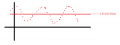
Adding a DC bias would not of itself change the amplitude of a signal related to its mean, nor would it change the peak-to-peak value, but the absolute peak values would be shifted. Thus a 5V peak signal shifted by 2.5V from a 0V reference would have peak values of +7.5V and -2.5V.
Here is the complete circuit and the explanation given with it. I found it in the internet. Its a circuit for digital guitar tuner. So, can you tell me whether biasing was necessary even though the circuit uses +5V and -5V.
Is dc biasing and dc offset the same thing? From my understand after reading these explanation it seems the same.
When an AC signal with 10Vpp biased at 2.5 V means, now the AC signal has +7.5V and -2.5V. So dc biasing means you make a point for the AC signal to oscillate instead of normal 0.
My microcontroller has an ADC of 5V (0 to 5V). The input signal is 25 mVpp. And I want to amplify it to 5V.
1) So I need an amplification of 200. (gain = 5000/25), right?
2) I need the amplification circuit to be powered by battery and should be portable. So, should I use single supply or dual supply using battery?
3) If I am using single supply, at which voltage should my biasing be and what should my +Vcc be? (I need output 5 Vpp, when the input is 25 mVpp)
Here is the complete circuit and the explanation given with it. I found it in the internet. Its a circuit for digital guitar tuner. So, can you tell me whether biasing was necessary even though the circuit uses +5V and -5V.
Is dc biasing and dc offset the same thing? From my understand after reading these explanation it seems the same.
When an AC signal with 10Vpp biased at 2.5 V means, now the AC signal has +7.5V and -2.5V. So dc biasing means you make a point for the AC signal to oscillate instead of normal 0.
Depending on the amplifier used, the +5V and -5V supplies may be required to obtain enough total supply voltage.
Although biasing to 0V might allow a bigger undistorted output swing, it may be appropriate to centre the output on +2.5V if it is necessary to feed something which only accepts positive voltages, for instance your ADC.
A DC offset is not necessarily the same thing as a DC bias, as I thought I had explained earlier. Some DC offsets are deliberately added to a signal, for instance to bring it within the input range of an ADC.
Other DC offsets are internal error voltages, due for instance to manufacturing variability in a differential amplifier etc. It can be difficult to reduce these accidental offsets to very low levels, and considerable effort may go into achieving this when it is required.
My microcontroller has an ADC of 5V (0 to 5V). The input signal is 25 mVpp. And I want to amplify it to 5V.
1) So I need an amplification of 200. (gain = 5000/25), right?
2) I need the amplification circuit to be powered by battery and should be portable. So, should I use single supply or dual supply using battery?
3) If I am using single supply, at which voltage should my biasing be and what should my +Vcc be? (I need output 5 Vpp, when the input is 25 mVpp)
Note that you cannot expect to get any voltage outside the range of voltages supplied to an amplifier, and in some amplifiers can only produce significantly smaller output voltages than their supply rails.
You must study the manufacturers data for the amplifier you expect to use to know what supply voltages will be needed: if the result is not what you need a different amplifier may be in order - for instance a "rail-to-rail" output type.
If you want minimum possible battery consumption, you may wish to use a a rail-to-rail amplifier biased to half its supply voltage. This solution might not give the best possible distortion performance, as the amplifier will be driven to its maximum capability.
Lower distortion may be obtained with higher supply voltages, but this method will require more battery power, and greater attention would be required to limiting the ADC input to a safe range - note that diodes to 0V and 5V may not necessarily be sufficient.
Can someone tell me a rail to rail op-amp that can be used with single supply 5V to 9V. Something easy and similar to LM358, also not that expensive.
I want to amplify a signal that goes to a micro controller ADC with 0-5V. So I want a rail to rail op-amp that use single supply so that I can bais it somewhere at 2.5V and still get 0 to 5V using a battery. I have found a couple of op-amps, which are: TLC272, LT1466, LM324N, TLV2771, LM6144. What could be the best choice, or is there anything that you suggest?
 Facebook
 Google
 GitHub
 Linkedin