need assistance in thevenin equivalent circuit

Thread Starter

yousifcyanide

Joined Nov 28, 2017
6
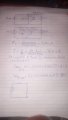
hey guys, I'm having trouble solving this question due to the ports placed in an unusual way.

I tried to approach it using source transformation which changed the load resistance into a supplementary resistor for the current/voltage source but I ended up missing a component for the equivalent circuit.

would really appreciate any pointing of flaws in my approach to improve my understanding.

many thanks in advance.
 

Attachments

Thread Starter

yousifcyanide

Joined Nov 28, 2017
6
Compare your hand drawn schematic with the in your first image.
yeah, there's a small mistake with the polarity of the voltage source, but the problem is regarding the 10k ohm resistor, should I consider as a load resistor or use source transformation with the current source.
 

JoeJester

Joined Apr 26, 2005
4,390
Does the original of your image include the whole question?

If you consider that 10k the load, remove it and do your calculations. You can use superposition to confirm your results.
 

Thread Starter

yousifcyanide

Joined Nov 28, 2017
6
Does the original of your image include the whole question?

If you consider that 10k the load, remove it and do your calculations. You can use superposition to confirm your results.
yeah it includes this question "
Find the Thevenin equivalent circuit seen from the terminals a-b.

I'll give superposition a go and post my results.
 

Thread Starter

yousifcyanide

Joined Nov 28, 2017
6
Does the original of your image include the whole question?

If you consider that 10k the load, remove it and do your calculations. You can use superposition to confirm your results.
I've used superposition after assuming the 10 K resistor as a load R, and it gave me the current through the other 10K resistor and the voltage across it. didnt help me in finding Vth.
 

Attachments

WBahn

Joined Mar 31, 2012
29,979
The terminals in the problem are drawn so as to strongly imply that the EVERYTHING in the circuit shown is to be part of the Thevenin equivalent. There IS no load shown -- any load would be directly between terminals 'a' and 'b'.

You are always free to redraw the circuit so that it looks more natural to you -- doing so can greatly reduce the chance of making strange mistakes. So draw a box with two lines crossing the right edge and put your 'a' and 'b' terminals there. Then draw the entire rest of the circuit inside the box. Now find the Thevenin equivalent of what is in the box.
 

WBahn

Joined Mar 31, 2012
29,979
isn't it an open circuit for current source and a short circuit for the voltage source?
In superposition you do multiple analyses such that each independent source is "on" in exactly one of the analyses. Commonly, if you have N independent sources, you do N analyses with exactly one different source turn on in each one. To turn a voltage source off, you replace it with a short. To turn a current source off, you replace it with an open.
 

JoeJester

Joined Apr 26, 2005
4,390
@WBahn,

It certainly appears that way. Those look like test points on the drawing, which made me think it could be the load. It would depend on how cynical the professor wanted to be with an introductory student. (Both assumptions on my part). The TS would be a few additional steps to make a second Thevinin circuit from the first with that 10k as part of the second Thevinin circuit.

@yousifcyanide

You can do it both ways to ensure your understanding. My initial thoughts were like WBahn's, however, thinking the diagram illustrated test points vice a connection, I went with the resistor as a load. These drawings are based on the assumption A and B are test points and the resistor is the load.

Thevinin-1.jpg Thevinin-2.jpg
 
Last edited:
Top