Need assistance from a Guru please. Identification process stalled....Icemaker board

Thread Starter

boydage

Joined Oct 7, 2016
92
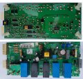
Hi. I have an icemaker in my kitchen that has popped the board twice. This is the second time and paying $350 for a new one is not cool, and infact these boards are so unreliable they are now unobtainable. But, I am kind of getting tired of digging into the box with my hands to get ice. Its winter in New Zealand....

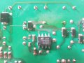
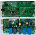
Anyways, looking at this little board, there is no power getting past the control transformer. Closer inspection I see the little comets tail of dust shooting out of one of the little diodes coupled into the TOP222G subcircuit. Testing it shows me 154k Ohms both ways, compared to 8m Ohms one way on the others around it. There are no identification marks on the top of this cute little number.

Does anyone have the time please to point me in the correct direction where I can identify a replacement for this little check valve? Also, would you recommend I change out the TOP222G as well?

I am basic electronic. But soldering in something to get power back onto this board would be well into my skillbase and just plain nice.

Regards
Boyd
 

Attachments

ebp

Joined Feb 8, 2018
2,332
The TOP222G is sometimes used with a conventional ultrafast recovery diode in series with a power zener type transient suppressor to clip the leakage inductance spike at turn-off of the internal FET (PI products don't tolerate avalanching). I suspect that is the ordinary diode and the transorb type is a through-hole component on the opposite side of the board. Figure 1 of the TOP22x series datasheet shows the typical arrangement, though the diode and transorb could be in the "opposite order" as long as polarity is correct. Sometimes an resistor-capacitor-diode (RCD) snubber is used (see Fig. 7 of the datasheet). In that case, the diode might be either ultrafast or a very ordinary diode (the circuit takes advantage of the slow reverse recovery of the diode to "suck" some charge from the snubber capacitor.

You need to have a close look at the top of the board in that area and see what you find. Please post a photo.

I probably won't have a chance to look again until about 20 hours from the time of this post, but others can probably help.

Just had another quick look - I think it likely to be an RCD snubber, judging by pad spacing for connected through-hole parts.
 

Thread Starter

boydage

Joined Oct 7, 2016
92
Hi ebp. Ok thanks for that. I actually have not heard of a RCD snubber before (being honest) but was wondering what the blue box component was on the other side of the board which I have uploaded a picture of.

Ok. I have it in my head now, that the components are installed in the middle of the connection between the transformer and the TOP222G. Is this to suppress the on/off current or emf the transformer would create on power up/down?

Looking at fig 7 of the data sheet, is the U2 PC817A the area we are looking at?

Anyways, I have uploaded an image. Many thanks for taking the time to help me out, absolutely no problem on time.

Rgds Boyd
 

Attachments

Hymie

Joined Mar 30, 2018
1,277
To have any chance of others helping you fault find the unit – I suggest you trace out the primary circuit, others will then be able to advise of expected voltages across various components, together with circuit resistance measurements that may identify the faulty component(s).

One (of many) problem you might have is getting the probes of a multimeter to various circuit locations with it connected in circuit (although you could power the PCB connecting Live, Neutral & Earth only, to observe the behaviour of the primary circuit).

The secondary control circuitry appears overcomplicated just to control an ice-maker.
 

Thread Starter

boydage

Joined Oct 7, 2016
92
Thanks Hymie. I can do that. The board has had a complete loss of power and you are correct about its complexity for an icemaker I almost programmed an Arduino to do the job something I can do.

The rogue component I have identified is one of the diodes in the primary power circuit that has no identification on it. As mentioned in my first post it is just giving a small amount of resistance each way whereas the others in the same circuit are definataly one way deals.The little diode in question runs to the drain leg on the TOP222G.

I have not put 230v onto the board yet. Given this component has been found faulty, and is in the portion of the board I was troubleshooting I am keen to replace it, and any others people may suggest, and see if the board powers up.

As requested I have outlined the area I am working in and the component I am trying to identify, along with which way to put the replacement in. Although the drain is voltage.... in? Fig 7 on the data sheet shows D1 UF4005. Perhaps its that one. Still in over my head.

Regards
 

Attachments

Hymie

Joined Mar 30, 2018
1,277
Thanks Hymie. I can do that. The board has had a complete loss of power and you are correct about its complexity for an icemaker I almost programmed an Arduino to do the job something I can do.

The rogue component I have identified is one of the diodes in the primary power circuit that has no identification on it. As mentioned in my first post it is just giving a small amount of resistance each way whereas the others in the same circuit are definataly one way deals.The little diode in question runs to the drain leg on the TOP222G.

I have not put 230v onto the board yet. Given this component has been found faulty, and is in the portion of the board I was troubleshooting I am keen to replace it, and any others people may suggest, and see if the board powers up.

As requested I have outlined the area I am working in and the component I am trying to identify, along with which way to put the replacement in. Although the drain is voltage.... in? Fig 7 on the data sheet shows D1 UF4005. Perhaps its that one. Still in over my head.

Regards
You have correctly identified the primary circuit area on the PCB.

Although you have identified what you believe to be a diode as faulty – it is very possible that the damage to this component was a secondary event of another component failure (such as the switching IC).
 

Thread Starter

boydage

Joined Oct 7, 2016
92
Thanks Hymie. Understood. The switching ic is a $3 part easily shotgunned in with a few minutes of soldering.

Back to initial problem. The shorted diode and its orientation.

Are you able to help how I can identify it? Because it is putting a stop to everything. I have looked at the chip data sheet and see a doide connected to the drain. Perhaps I will just follow the sample circuit there and see what happens. It looks similar the way its connected onto the leg of the transformer. I seem to remember reading somewhere it uses pwm to control the voltage?
 

ebp

Joined Feb 8, 2018
2,332
The diode in question is quite clearly in an RCD snubber. If you look at the datasheet for the TOP device you will see a typical arrangement - a resistor in parallel with a capacitor and the diode in series. Note that that network is directly across the "primary" of the "transformer" (it isn't a transformer in the usual sense, but that doesn't matter here). The resistance of the primary of the transformer will be a few ohms, at most. When you try to measure the resistance of the diode in-circuit with a meter that applies a voltage too low to make the diode conduct, what you are actually measuring is the value of the resistor in the snubber. R47 is the snubber resistor. I can't really tell what the color bands are, but they look like brown - green - something.
If the "something" is yellow, then it would be 150k ohms - as you are measuring. I sort of looks more like the something is orange, but ...

If you have meter with a diode checker function, which will apply enough voltage to make a diode conduct and display the voltage, try that. You should get around 0.6-0.7 volts one way and probably "open circuit" the other.

Check the resistance between pin 5 of the TOP and any of pins 6 to 8 (see datasheet). If the TOP has failed, the most likely failure is a short-circuit between these pins.

Removing surface mount parts from that board won't be very easy. It looks like they have been glued in place (not little gobs at the sides of each) so that the whole board can be wave soldered (all those poor little parts actually covered in molten solder - seems mean, but it is fairly common).

It sort of looks to me like there are markings on the diodes. It is typical to only have two or three characters, which can make it difficult to identify what they are because there is no industry-wide standard. Each manufacturer comes up with their own code, though different mfr's of the same part do often use the same code.

R6, 13, 16 & 17 are odd - the color code suggests they are 10 megohms - which is extraordinarily high. The last band looks like it is yellow, and I don't know offhand what that means. It certainly isn't a common tolerance band color.
 

Thread Starter

boydage

Joined Oct 7, 2016
92
HI EPB. Ok.

You were correct, once I put a decent meter onto that diode it did bring it to function correctly. I also measured for a short between legs 5 to 6/7/8 on the TOP and got megohms. The legs 1,2,3,6,7,8 - now they are almost all common - with 0.3 ohms between all of them. Well, I measure them as a short. Have I found something or is this a characteristic of this TOP device?

The resistors you mentioned were just under 10megohms.


D10. Now that little doide gave me 0.775v one way and 0.395v the other.The resistor next to it is not in parallel but one of the legs is the same.

Out of the research I have done on switching power supplies most times it has pointed to the capacitors and shotgunning them by changing them all out has worked in the past.

I am unsure where to go next. I have not plugged it into 230v yet as am keen to avoid that although I am an electrician. Main reason besides not wanting a hot board on my bench is I dont know exactly where to measure the output voltage of the primary side of this board. Would I look to the other side of T1 and expect to get 5v?

I really want to fix this.....
 

ebp

Joined Feb 8, 2018
2,332
It sounds like the diode and the TOP device are OK. Pins 1-3 and 6-8 are all connected together to the "source" of the FET internal to the part. Pin 5 is the "drain". A drain to source short is a common failure and since you are measuring megohms, that is not the case (there is a slight chance that it first failed short-circuit then opened like a fuse, but that often causes the package to split or blow apart rather violently).

There is a possibility that capacitors have "worn out." [EDITED - don't know what happened, but what I wrote made no sense to me!] Electrolytic caps do wear out and decrease dramatically in value. Behavior of the circuit is then unpredictable, especially with the TOP devices. It is very common for such caps to show signs of overheating and frequently the vents (the indentations in the tops of the cans that supposed to open "gracefully" to prevent the can from exploding or launching like a rocket) are opened. None show any sign of that.

The large brown-sleeved cap next to C30 is the main filter capacitor for the rectified AC input. It should have something around (1.2 times your AC line voltage) VDC across it. C23 is probably the main filter capacitor on the secondary side. The voltage on it probably matches the coil voltage of the relays.

I don't see a fuse on the AC input to the board. If there isn't, and you decide to power up on the bench, I recommend using an fuse in the AC input. A low-current time-delay type (say 1/4 A to1 A) should be OK - just something so that if something on the board does short the line you don't burn tracks off the board.

There is an oddity - adjacent to C1? (second digit covered by the squarish paper label) there is a surface mount resistor soldered on the top of the board. I would inspect this closely to confirm it is properly soldered. One end looks OK, the other looks like it may be dubious.

The diodes probably are laser marked and the conformal coating on the board has obscured the markings. You might be able to make out something with a good magnifier and strong light. I can't even see the cathode marking band that as normally across one end of the body in the photos.

Do wear eye protection if you power the board up. As I mentioned, sometimes things go bang and can launch bits.

If the power supply turns out to be OK, it is going to be very difficult to proceed. There is an awful lot of circuitry on that board and a microcontroller with a lot of pins.
 

Thread Starter

boydage

Joined Oct 7, 2016
92
Ok thanks. Time to put some power on it. Will pickup a small fuse prior. I was just inspecting the board out in the sun. Underneath R47, the leg adjacent to C27 especially looks like its been hot.

This board was working. It never came alive again after the main switchboard in my house was powered back on after maintenance was done to the household supply. I cant but help thinking that it will surely be the power supply in this case. I will go deeper and thanks for the H&S advice. All fun and games until.....

You are correct, if the power supply turns out to be ok there is no way I am even entertaining the idea of repairing the rest of it.
 

Thread Starter

boydage

Joined Oct 7, 2016
92
Just out of interest, R47, how do the colours appear to you? I get 157.9 kilo ohms. But for the life of me cant decide what the colour of the third band is either light brown, tan.
 

debe

Joined Sep 21, 2010
1,389
R47 is probably 15ohms or 150ohms, it is used as a fuse, as its the main power feed to the transformer..Full Board2.jpg
 

debe

Joined Sep 21, 2010
1,389
If you are going to use a fuse use at least a 2A slow blow as SMPS start up current can be quite high.
 

Thread Starter

boydage

Joined Oct 7, 2016
92
Hi. The resistor outlined. R47. Measures 160k ohms. Thats way to high huh? But I cant fully identify the last band to be sure what to replace it with. Thoughts?
 

ebp

Joined Feb 8, 2018
2,332
I think R47 is likely nominally 150k (brown green yellow) and the yellow band has discolored. It is the resistor in the RC snubber, and that value should be about right.

It is not terribly unusual to use a flameproof fusible resistor to do double duty as a safety fuse, but it would normally be somewhere much closer to the AC input - typically ahead of the bridge rectifier and more usefully right at the AC input, before the MOV. The appearance of R47 suggests very ordinary carbon film type, not a flameproof fusible type.

It looks like the main input filter capacitor is only 10 µF, so, while the peak inrush current may be quite high, the duration will be very short.

I think I may have located the "fuse" but I can't tell for sure because of the conformal coating. If you look at the side of the board with the SM components near the plastic mounting standoff in the lower right corner, it looks like there is a very narrow copper track as one arm of the <-shaped tracks just above the standoff. The intent would be that this track would melt to do the job of a fuse, at least to prevent fire (which is pretty much the only thing a fuse on the input to a switcher is ever of any use for).

Failure of something that had worked OK before power-down when power is reapplied is not unusual. Power-up tends to be a time of high stress for a number of components. Along with that, thermal cycling can cause failure - everything is OK when running "hot" but if you allow it all to cool then heat it up again, sometimes something "breaks."
 

Thread Starter

boydage

Joined Oct 7, 2016
92
Thats what I suspected about R47. It looks like it runs quite warm actually when I look at the board outside in the day light so yellow makes sense.

I read that last post and didnt even get my pants on before I had the meter out checking that little wasted section in my undies only to create the QBL (quivering bottom lip) when I see it is still intact.

All that makes sense. I will put some line voltage on the board today. Have been putting it off. Mostly because accessing a decent contact with my meter requires the pressure breaking through the coating. Will have to mount the board on something stable.

I think that finding the power supply operational though is the stop point. Hoping its not. I will check for volts as per previous posts. Have a 2A fuse although its a standard one.
 

ebp

Joined Feb 8, 2018
2,332
A 2 amp non-delay fuse should be fine. It should easily survive the power-up spike but still blow readily before anything on the board would.
 
Top