Hi sir,
I want to know two things in this circuit.
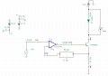
1. we are using two op amps for gain multiplication and observing high current variation.......?
first one is unity gain buffer amplifier, second one deal with transistor nonlinearities. is it right?
2. we are using feed back from emitter to inverting terminal. why?
Hi sir,
I want to know two things in this circuit.
1. we are using two op amps for gain multiplication and observing high current variation.......?
first one is unity gain buffer amplifier, second one deal with transistor nonlinearities. is it right?
2. we are using feed back from emitter to inverting terminal. why?
1. Not really for gain multiplication. The first one adds an offset to the incoming signal.
2. The second one closes the loop around emitter current which is with 1% of the collector current -the current is proportional to the voltage across R6 which is what is sensed and fed back to the inverting input.
No, you don't need to apply any offset other than what you mentioned in your post #5.
"Minimum is 18 mA 1.8 voltage, maximum is 35mA , 6 v(linear region)"
The offset is only so that you get the input voltage to output voltage relationship that you specified. The second opamp closes the loop around the transistor's offset so the transistor's offset has virtually no effect.
previous circuit working fine. but now i want to change laser (Threshold 2.2 V ,210mA-maximum 3 V 300mA) . so which component i have to change in this circuit.? This is Green laser pointer. i want to operate at 250 mA bias , 1V peak to peak.
Thank you
You can re-scale the output current range to reach 300 ma by changing the transistor to a KDT882 and heatsinking it, and also making the emitter resistor 15 ohms, use the 2 watt size.
The things that make the KDT882 special is the fairly high gain and wide bandwidth in a package capable of dissipating several watts, in this case, up to two watts.If you can find heatsinks with specified thermal resistance to ambient, look for one with less than 25 °C/watt.
Hi sir
this is the modified circuit for my understanding, so you saying change 2n3904 replace ktd882. and place on the heat sink.
is it right?
if i place 15ohm resistor is it will burn? .because i tried with 2n2222A transistor 21 ohm resistor, resistor got heated.
i changed 2n3904 because Ic is 100mA only. but 2n2222A is 800mA.
is it ktd 882 only or other any transistor suggest please (if might not available)
SomiuBabu wrote: this is the modified circuit for my understanding, so you saying change 2n3904 replace ktd882. and place on the heat sink.
is it right?
Yes.
SomiuBabu wrote: if i place 15ohm resistor is it will burn? .because i tried with 2n2222A transistor 21 ohm resistor, resistor got heated.
i changed 2n3904 because Ic is 100mA only. but 2n2222A is 800mA.
If you replace the resistor and the transistor it should not burn. The reason the transistor has to be replaced is that the 2N3904 and other transistors that size cannot dissipate the power (300 ma x 6 volts = 1.8 watts) without getting too hot.
SomiuBabu wrote:
is it ktd 882 only or other any transistor suggest please (if might not available)
You can use another transistor with similar properties. The trick is finding one with similar properties that is available to you. As I wrote in Post #31 "'The things that make the KDT882 special is the fairly high gain and wide bandwidth in a package capable of dissipating several watts, in this case, up to two watts.If you can find heatsinks with specified thermal resistance to ambient, look for one with less than 25 °C/watt."
If you find something that is available to you one of us here can evaluate it as a replacement for the KTD88s in this circuit. I bought some from Electronic Source in Bangkok. You can see it and download the datasheet from here (In U.S. $ the price is about US$0.13) : http://www.es.co.th/detail.asp?Prod=013601815
I think the 2SD1361 would work if you don't need the 500 kHz bandwidth. If you need that kind of bandwidth, most Darllingtons will probably be too slow. Simlarly, MOSFETs capable of handing 300 ma have high capacitance that would be likely to cause the circuit's response might be peaky or even oscillate.
You might be able to get the circuit of Post #32 to work if you are lucky -you need 3V for the LED and you will have some voltage across the transistor, so realistically that would leave you with about 1 volt for R7 the emitter resistor. For 300 ma the resistor would be 3 ohms 1/2 watt. Also remove R42, and change R4 to 100 ohms.
The B772Y looks pretty good. If the LM318 oscillates try about 15 pf between pins 1 and 8 to reduce the frequency at which its internal gain starts to decrease. The 15 ohm resistor should be rated at 2 Watts.
I should have put it in the schematic, but for a wideband ampl like the LM318 you should also put a 0.1 uf ceramic capacitor from pin 7 to pin 4.
hi sir
i tried to implement circuit
but op amp is getting saturated. output showing the nearly same voltage of supply. resistor at emitter is getting too hot we used some parallel 5 hundreds. transistor base getting the same voltage similarly emitter also.
 Facebook
 Google
 GitHub
 Linkedin