Need a schematic for a MOSFET switch

Thread Starter

fredric58

Joined Nov 28, 2014
252
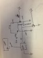
I need to control a 5v breakout board. Turn it on with a logic high from my arduino. (A pulse) Turn it off with another logic high. (Pulse) Using 3.3v. I have found examples but don't know how to figure which mosfet and resistors to use. Can anyone help out. thanks
 

crutschow

Joined Mar 14, 2008
38,504
What you need is determined by the current taken by the breakout board.
You can use a P-MOSFET of sufficient current capacity (a least double of what the board takes) with an NPN transistor driver.

Why is the signal a pulse from the Arduino?
Can't you leave it high or low?
If it's a pulse, then you will need to add a flip-flop or latch to maintain the state.
And will you then need to know that state (whether the breakout board is on or off)?
 

Thread Starter

fredric58

Joined Nov 28, 2014
252
What you need is determined by the current taken by the breakout board.
You can use a P-MOSFET of sufficient current capacity (a least double of what the board takes) with an NPN transistor driver.


Why is the signal a pulse from the Arduino?


Can't you leave it high or low?
If it's a pulse, then you will need to add a flip-flop or latch to maintain the state.
And will you then need to know that state (whether the breakout board is on or off)?
you are correct, sorry I didn't better explain it. trouble with my computer at the office.

I have a PIR, runs on 3.5 - 5 v, has a 3 v output when triggered. and has a quiescent current of around 55uA when in it's idle state, that's all I know about it.
and YES I need a 2 mosfet latch switch. I need to turn the PIR "ON" right before the 328 chip goes into POWER_DOWN_MODE. as I understand it you just need to pulse a logic high and it will stay on until another pulse is received and it will turn off.

I have seen examples of these latching switches, but they are not fully explained. hope that better explains. thanks
 

Reloadron

Joined Jan 15, 2015
7,889
Turn it on with a logic high from my arduino. (A pulse) Turn it off with another logic high. (Pulse) Using 3.3v.
What you seem to be describing here is a flip-flop and to be more specific a D Flip Flop where a single pulse turns on an output on the leading edge of a pulse and the leading edge of a second pulse turns it off. Pulse On and Pulse Off is what I see. Now if you can provide a link to any of the circuits you mentioned I am sure someone here could explain it to you and give you some ideas. You are turning the PIR sensor ON and Off using an Arduino?

Using two MOSFETs P-type (PMOS) and N-type MOSFET (NMOS) you can buils a latching circuit. Most online examples of this sort of circuit reflect using a button but a button switch can be likely be replaced with a transistor in many applications.

I see Analog has replied as I crawl along here typing and taking the dogs out. Analog, I believe his 328 reference is to an Atmega 328P as used on Arduino Uno and other boards as the uC.

Ron
 

ebp

Joined Feb 8, 2018
2,332
Do you know what the maximum operating current of the PIR board is?

If it is only a few mA, you are running it from a 5 V supply, and given the supply tolerance of the PIR board, I'd run the PIR board directly from the output of a suitable flip flop (JK or D if you want the on & off pulses to come from the same output; RS if you want to use two outputs) and call it good. 74HC (or HCT if the clock swings to 3.3 V max) or AC/ACT will cheerfully source several milliamps to at least 3.3 V from a 5 V supply. If you make an RS flip flop from 2 gates in a quad package, you could use the other two in parallel as buffers, if there was nothing better to do with them.

Since there is talk of two FETs to make a bistable, the assumption is that there are separate set and reset signals available. You must either use diodes to OR gate drive or use the set and reset signals to directly momentarily supply the full current to the load - which should be no problem.
 

crutschow

Joined Mar 14, 2008
38,504
How will you insure that the pulse is in sync with what you want to do?
Can you have the 328 (I assume that's an ATmega328) output pulses on two different lines, one to turn the PIR on and one to turn the PIR off?

When exactly do you want the PIR on and when exactly do you want it off? That's rather vague from your description.
We need to know the exact problem you are trying to solve so we can provide the best solution, not how to effect your solution.
 

Thread Starter

fredric58

Joined Nov 28, 2014
252
Your questions lacks a lot of details. For example, what is a 328 chip?

Can you post a wiring diagram of your system?

ak
a 328P-PU is the chip in an arduino. I use a bare bones, that's just the chip, (2) 22 uP caps and a 16mHZ crystal for the lowest power consumption in POWER_DOWN_MODE possible. about (2) uA's.
 

Thread Starter

fredric58

Joined Nov 28, 2014
252
How will you insure that the pulse is in sync with what you want to do?
Can you have the 328 (I assume that's an ATmega328) output pulses on two different lines, one to turn the PIR on and one to turn the PIR off?

When exactly do you want the PIR on and when exactly do you want it off? That's rather vague from your description.
We need to know the exact problem you are trying to solve so we can provide the best solution, not how to effect your solution.
it's a LATCH circuit, it doesn't need 2 different lines. once you turn it ON, it stays "ON" till you send another logic HIGH. when "exactly" that is as explained. right before the 328P-PU chip goes in to POWER_DOWN_MODE. write the pin HIGH, turn on the PIR, 328 goes to sleep................it will get turned off later. (the PIR)

the exact problem....is not a problem, I just don't know how to wire it. you have (2) mosfets, a couple resistors. not that complicated. a signal from the arduino/328 chip activates a mosfet, that mosfet turns on the power supply to the PIR. "LATER" the arduino/328 sends a signal to the "other" mosfet and it turns the PIR OFF. (like a FLIP - FLOP)

in an N channel mosfet switch, if you charge the gate it turns on the mosfet. if you discontinue power to the gate it still is on. (if you don't have a pull down resistor) the 2nd mosfet, when charged lets the first one go to ground, and that turns it OFF.

it's just a two MOSFET ON/OFF switch. activated by a logic high from the arduino. the first high turns it on, the second turns it off. nothing magic. I just don't know enough to make a schematic. or what components to use since it is such a low power project.

to simplify it. I need a MOSFET switch. a high logic "pulse" from the arduino/328 turns something on. ANOTHER high logic pulse from the arduino/328, turns that thing OFF. on/off, flip/flop, with mosfets

: )
 

crutschow

Joined Mar 14, 2008
38,504
you have (2) mosfets, a couple resistors. not that complicated. a signal from the arduino/328 chip activates a mosfet, that mosfet turns on the power supply to the PIR. "LATER" the arduino/328 sends a signal to the "other" mosfet and it turns the PIR OFF. (like a FLIP - FLOP)
Sorry, it's still clear as mud.
Why do you have two MOSFETs?
What power supply?
Are you turning the power supply on and off or the power out of the supply?
How are you going to sync the flip-flop with the micro output pulses (a push button)?
What power is available for the flip-flop?

Since a picture is worth a thousand words, please draw a simple block diagram of what you have and post it here.
The game of 20 questions is not working.
 

Thread Starter

fredric58

Joined Nov 28, 2014
252
you are familiar with a 1 button PUSH ON / PUSH OFF switch circuit?

Replace the button with a latch switch where a momentary logic high turns it on and another momentary high to turns it off.

5v power supply.
 

Attachments

crutschow

Joined Mar 14, 2008
38,504
I don't understand what all the transistors are doing. :confused:

So below is a circuit using a flip-flop driving a P-MOSFET to control the 5V power to the PIR.
Q1 converts the 3.3V pulse to 5V required by the FF.
The circuit changes state on the falling edge of the input pulse.
SW is a push-button switch to manually reset the circuit to off and synchronize it with the pulse from the 328.
If you want to have the PB turn the PIR on instead (or also), connect the PB and resistor to the CLR input instead of the PRE input (ground the PRE input if unused).
upload_2018-2-20_9-22-16.png
 

Thread Starter

fredric58

Joined Nov 28, 2014
252
all those transistors?, but no buttons. it's really a simple circuit.

5v goes thru R1 to the p-ch MOS gate, this holds it in the off state.
a 2ms logic high from 328 D6 to T1 pulls the p-ch gate low and turns on the power to the PIR. (it's ON state)
at the same time it sends current to the gate of the N-ch MOS turning it on and that holds the p-ch gate LOW.
when you want to shut off the PIR. or reset.
send a 2ms logic high to T2
which pulls the current from the n-ch MOS gate to ground , which shuts off the n-ch MOS.
which returns current to the gate of the p-ch MOS. which is (it's off state). and it only draws only a minimal amount of current.

AND, it can be done with only 1 logic pin, by reading the current state of the n-ch gate and flipping it. but that's another story.


buttons are fine if someone is there to push them. i'll be off somewhere drinking a beer.
 

Attachments

crutschow

Joined Mar 14, 2008
38,504
AND, it can be done with only 1 logic pin, by reading the current state of the n-ch gate and flipping it. but that's another story.
That circuit is a mess and can't work.
But since you seem to have it all figured out, you certainly don't need my help.
buttons are fine if someone is there to push them. i'll be off somewhere drinking a beer.
That apparently explains your circuit design. :rolleyes:
 

Thread Starter

fredric58

Joined Nov 28, 2014
252
I'm curious, why do you say it won't work? and that it is a mess. I'm a novice at this, however it works very nicely. what seems to be wrong with it?
 

Dodgydave

Joined Jun 22, 2012
11,395
Your N-fet is wired wrong, the Source goes to gnd, the Drain to the collector of the Npn..


Your circuit is just a Thyristor using two fets, N and P type....What's wrong with using a simple Cd4013 gate??
 

Thread Starter

fredric58

Joined Nov 28, 2014
252
NO...........The GATE goes to ground to shut it OFF.(the N-CH MOSFET) check your work. it's a "LATCH" switch.

what happens when you turn OFF the voltage to the gate of a N-CH MOS?

It turns OFF, correct? and on a P-CH MOS when it's high it's OFF and when the gate is LOW it's ON.

Correct? or are all the experts on the WEB nuts? I'm a novice not an engineer of electronics. Just trying to solve a challenge.

if you simulate it in spice or something similar it seems to work fine. I will make one this weekend to double check it. but theoretically it works well.

"What's wrong with using a simple Cd4013 gate??" explain how I works with pictures and I will be happy to check it out. I came here to learn something, so far....zilch!

Thanks
 
Top