Need a proper transformer for a SMPS circuit design ASAP!

Thread Starter

Mohamed Shabrawii

Joined Jan 1, 2018
4
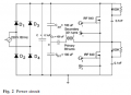
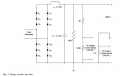
Hey guys, I'm working on a SM power supply circuit which has 220 vac /50 Hz input and the result should be 1000 V 0.3 A, The required transformer will be after the first rectifier circuit connected to a Half-bridge inverter circuit with operating frequency 20 KHz at 45% duty cycle, the input of the required transformer will be about 320 V in DC ( 220 vac after full-wave rectifier circuit ) and with output of 1500 V and 0.6 A. Note that the primary winding are 39 turns and the secondary winding is 321 turns. Please if you have any information about the required transformer tell me about it, thanks in advance.
 

Attachments

AnalogKid

Joined Aug 1, 2013
11,038
A 400 W 1 kV transformer is *not* a simple design. Starting cold without a similar previous project to adapt, my guess is that the transformer will take around 4-6 months to design, prototype, and document for production. 3 months absolute minimum IF you already have a qualified magnetics company ready to go at a fast pace.

There is an error in the power 1 schematic.

ak
 

Thread Starter

Mohamed Shabrawii

Joined Jan 1, 2018
4
Can you give me more information about the error on schematic Power 1.
I have downloaded this power supply design and it says it worked properly, I thought about the transformer of cfl Lamp circuit, can it operate as the required transformer? or can I make the required transformer by myself or it's too complicated ??
 

Alec_t

Joined Sep 17, 2013
14,313
I thought about the transformer of cfl Lamp circuit, can it operate as the required transformer?
Definitely not. A CFL is rated at only a few Watts and you are hoping for 1500V x 0.6A = 900 Watts !:rolleyes:
More importantly, projects involving mains voltage (and certainly 1500V) can be LETHAL and are unsuitable for inexperienced hobbyists :eek:.
Welcome to AAC!
 

Thread Starter

Mohamed Shabrawii

Joined Jan 1, 2018
4
Definitely not. A CFL is rated at only a few Watts and you are hoping for 1500V x 0.6A = 900 Watts !:rolleyes:
More importantly, projects involving mains voltage (and certainly 1500V) can be LETHAL and are unsuitable for inexperienced hobbyists :eek:.
Welcome to AAC!
what are safety considerations to keep in mind, when I (have) to design circuits that produce 1000V, every inexperienced hobbyist have to gain experience by implementing such projects, thanks in advance.
 

Thread Starter

Mohamed Shabrawii

Joined Jan 1, 2018
4
1000 V at 0.3 A vs. 1500 V at 0.6 A - which output is which, and why?

ak
as you can see after the first rectifier circuit there is a half-bridge inverter circuit with the desired transformer which is designed to have an output of 1500 V and 0.6 A then the output of that transformer is the input of the second rectifier circuit then the output of the whole circuit will be 1000 V at 0.3 A.
 

dendad

Joined Feb 20, 2016
4,476
I suggest you give this project a miss. It it extremely dangerous and as has been stated before, not simple.
Switch Mode Power Supplies are actually quite complex beasts and the higher the power the more unforgiving they can become.
Also your design description so far does not make a lot sense to me. And some of your questions indicate you should leave this well alone.
Electronics is a great hobby and career so do keep at it, but please start with something more realistic and less likely to kill yourself or worse, others.
 

Alec_t

Joined Sep 17, 2013
14,313
what are safety considerations to keep in mind
If you have to ask, then you clearly should start by researching the necessary safety precautions.
inexperienced hobbyist have to gain experience by implementing such projects
No, they don't. They should gain experience on low voltage projects and demonstrate that they fully understand the hazards involved with high voltage projects before embarking on them.
 

AnalogKid

Joined Aug 1, 2013
11,038
I agree with the comments above. Rather than start with a 1500 V, 900 W monster, try a 12 V, 1 A supply you can use to power other experiments.

If you want to do a switching supply, some of the more common controller chip companies have arrangements with transformer companies to produce transformers designed specifically for their chips in popular power sizes.

ak
 

Janis59

Joined Aug 21, 2017
1,849
RE:""what are safety considerations to keep in mind""
1) Anything is under phase voltage. Thus any constructive must have a double insulation in the primary and grounding
2) All the measurements and soldering must be done at disconnected circuit AFTER the capacitor tank capacitors are dis-loaded by special stake with resistor
3) All measuring devices must have a floating battery feed or at least an insulation transformer
4) The oscillo cabling must be 3kV rated with 1:100 divider (them are quite expensive Chinese what are incredibly weak mechanically, or ultra-expensive if from normal producer)
5) All insulation of secondary must have at least 2 mm of sheated insulation or 4 mm in free-air conditions. Better to apply 6...8 mm, especially from coil both sides.
6) The wire for secondary winding must have a double insulation or/and it would be winded with step, say one mm. For that case to secure the step width the best material is fishing thread.
7) The HV coil must be vacuum-infused into epoxy, if that is not intended to be `use three days and then throw out` circuit. Infusion is doable in kitchen, using the plastic bag, scotch (not those what for drinking :) ) and rotary forvacuum pump or at least the vacuum cleaner. Wrap the bag, work in the two pipes, one is to vacuum pump and another to bin with mixed epoxy. Without of this some impurities or humidity works a place where permanently goes MICRO-sparkling, thus building a burnt channel for more serious short-circuit. It happens gradually, months/years long, if voltage is near 1 kV or more.
8) Apply a correct damping circuits to DS, otherhow by a kilogram of mosfets top shift it every 15 minutes.
9) Apply a correct gate measures to prevent an oscillation. If it starts, see for trash bin and new order of components.
10) Apply a rather too large security time gaps between gates than too small, other-how together with mosfets You are going to buy a new power substation for all Your street-bloke.
11) Apply a topology for Vcc cap bank giving extra tiny parasythic inductance. Otherhow illustrative V=di/dt gives 50Amp/10 nsec =5 Gigavolts, what for sure will kill all semiconductors around and not only that. Thus make a thumb-rule - everywhere bifillary sandwich lines, everywhere as short as possible (even 1 cm is too large), the best is double-plate type constructive. Secure the cap bank with high frequency smaller caps straigh on the FET D-gnd feets. Even one milimeter here has importance. Often 0,01...0,1 mkF is enough here, most cases.
12) Apply a best available solutions for overcurrent detection and flash-speed security shutdown in case of primary overcurrent, primary throughput current, thermal of FET, output voltage, output current, shortcome in output etc security circuits, as well the phase to output security system. Without of that all You may play with 10 Watts, but not 1 kW. Existance of one security circuit not means that other one may forget.
13) Think three times (three!) about how to dislock the EMI effects on gate and gate drivers/controller. If not, then don`t be surprised. You have large di/dt source just there where milivolts of signal loop is processed. It shall not pardon the any inaccuracy in ecraning/briding/ground-loops etc.
 
Top