Need 3-Position Toggle Switch Help - Old DC Trolling Motor

Thread Starter

PHIL TUGGLE

Joined May 22, 2015
7
I am trying to fix it up an old 12 volt trolling motor for my son, and am stuck. Can someone help figure out what wire goes to what terminal?

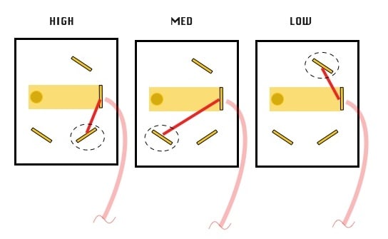
The unit just has two 3-position toggle switches for control; FWD-OFF-REV and HIGH-MED-LOW. I am pretty sure I understand the first switch, but it must be coupled with the second switch and the motor in such a way that I do not understand. Just do not want to fry anything by guessing.

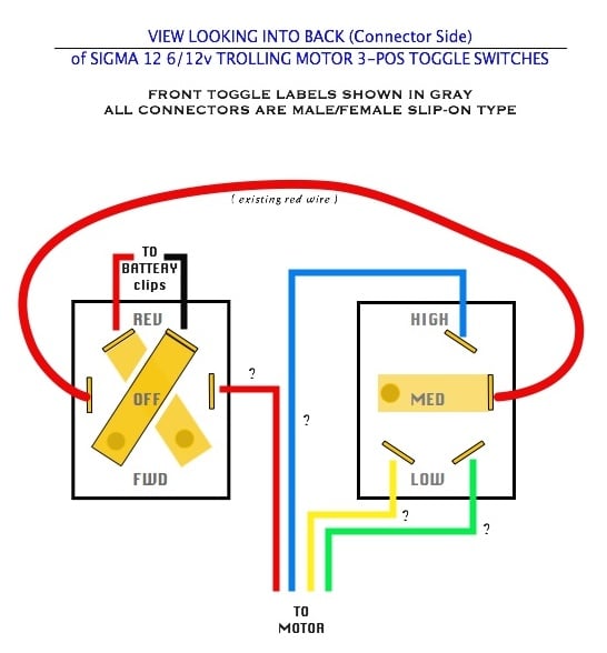
The FWD-OFF-REV switch has 3 unoccupied terminals, and the HIGH-MED-LOW switch also has 3 unoccupied terminals. Here is a sketch showing what I have:


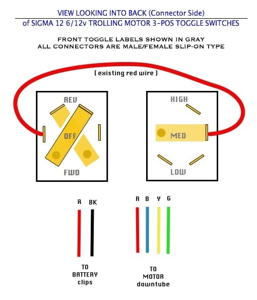
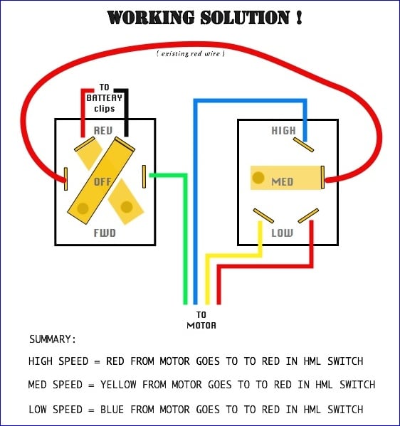
The root cause of the problem (aside from my own lacking knowledge) is that someone has detatched all the wires from the back of the two switches, except for ONE red (power I presume) wire that ties the two switches together. There are two wires available from the battery clips, black and red. And there are four wires available from the DC motor, red blue yellow and green. I cannot see where these connect to the sealed motor; these 4 wires emerge from the downtube.

Does anyone know what wire goes to what terminal? After searching online for several days, and calling the current manufacturer (who surprisingly had no clue - citing product age as the problem), I hope someone in this great forum can help.
THANKS!

Phil
 

Stuntman

Joined Mar 28, 2011
222
I know nothing of this particular unit, but will tell you some things that may help.

A.) Use an Ohmmeter to figure out what connections are being made with each switch position in both switches.

This should make the first switch pretty easy. Going from forward to reverse should, if it were my guess, reverse the polarity of the "output" terminals, whichever they may be. Off, should leave these outputs "open" contacts.

B.) Once you have gotten the F-off-R switch figured out, it appears the second switch connects the positive or negative (most likely determined by whichever happens to be connected via the first switch) to one of the B,Y,G wires (For instance, low=feed blue, medium=feed yellow, etc). OR, perhaps the positions feed more than one at same time (ie, low connects 12V to Blue, Medium connects to Blue AND yellow... Again, mapping this switch with a voltmeter will tell you a lot.

C.) Considering you have a bipolar motor setup, you can do some trying around without too much risk of burning things up. Of course, this is one big gulp of a theory solely from this diagram.

Map the switches and come back if you get stuck.
 

Thread Starter

PHIL TUGGLE

Joined May 22, 2015
7
Thanks, Max and Stuntman --
Well, I was able to get a continuity check on the HIGH-MED-LOW switch, and here is the result showing the only things that got a reading. In this diagram, a red line indicates where continuity was found when the switch was in the labeled position. The pale red wire is the one that goes over to the other switch in the original diagram ...


It is interesting that in all three positions, the continuity read around 2 ohms in each case; does that mean there is no resistors in the switch?

Referring to the first diagram at the beginning of this thread, I am still no closer to knowing what to do. I hope this new information offers clues to someone.
 

Thread Starter

PHIL TUGGLE

Joined May 22, 2015
7
Okay, in compliance with the last suggestion, here is how the FWD-OFF-REV switch showed continuity, AND the results on the motor...which surprised me. Everything will connect to everything, at least when connected one-by-one with the meter.

Here is a diagram for the switch (I chose to use black and red - so those are not wires), and a table for the four downtube wires to the DC trolling motor.


Can anyone chime-in on the correct way to hook things up now?

Even more stumped than ever -
Thanks
Phil
 

shortbus

Joined Sep 30, 2009
10,045
On the F/R switch, I'd say the red and blk battery wires go to the top (angled) terminals.

Not sure what you were showing with the down tube(motor) wires. One of the colors should be common with all the others. for a return path to the remaining terminal of the F/R switch. Motor probably has three sets of coils and connects them in series to get different speeds.
 

Thread Starter

PHIL TUGGLE

Joined May 22, 2015
7
Thank you shortbus! ...Maybe I can make some progress now. No doubt, my colors are wrong (there are many possible combinations), but Is the following diagram going in the right direction? Is anything RIGHT about it?

Possible Solution?


Man, it would sure be easier just to find somebody that HAS this doggone trolling motor, and then just go look at it. Ha! Too old. Antique...like me.

Thanks
Phil
 

ErnieM

Joined Apr 24, 2011
8,377
For this motor there are no resistors needed for different speeds: the motor itself has different coils to run at different speeds. Actually it is one big coil for the max speed, but has extra taps added for the other speeds.

To figure out which downtube wire is which you need a set of actual resistance measurements, as opposed to the check marks in yout table. I do suspect your meter showed all the same low values so this mat need plan B.

Plan B is to take a reasonable guess, and the only line you are guessing on is the one of four downtube wires that goes to the reversing switch.

I would guess as you did that is the red wire. The other wires will sort themselves out soon enough. Here's how I would do it:

First I would look for something other than a 12V battery to power this. A big wall wart supply may be enough as you want to just run the motor in air (not water), which takes lots less current than moving a boat. This way any mistakes will not burn out the motor (a battery can deliver enough power to melt wires or weld metal.)

Connect together and try all 3 speeds. The first cut you want to go slow and let the motor fully stop before trying the next speed. If all three speeds turn the same way you have the wire to FWD/OFF/REV correct. If any one of three spins the other way swap that wire on speed control with the wire on direction.

Once all three speeds go the same direction use your ears to see if slow, med and fast speeds sound right. Swap wires till it is right and that should be it.
 

Thread Starter

PHIL TUGGLE

Joined May 22, 2015
7
Thanks, ErnieM - and thank you all! NOW we are getting somewhere.
Gonna try this before tomorrow morning and will come back with results.
 

shortbus

Joined Sep 30, 2009
10,045


Man, it would sure be easier just to find somebody that HAS this doggone trolling motor, and then just go look at it. Ha! Too old. Antique...like me.

Thanks
Phil
The motor is a Shakespeare but a quick online look didn't show a manual. They changed hands a few times over the years. Ernie's idea is how I would proceed try to figure it out. Even a battery charger might work if no wallwart.
 

Thread Starter

PHIL TUGGLE

Joined May 22, 2015
7
Happiness! Solved.
After messing around with a small 6 volt battery, here is the solution I found THANKS TO YOU GUYS !

(Remember that the gray labels are throw positions on the front of the switch, so these are diagonal to the contacts inside the switches)


I know it is a dinky project, but I am really happy...as will be my son...and HIS son!

I want to thank you all again, but have one more question:
Can someone please explain how this apparent coil scenario works? It is really cool, but mystifying and I want to learn what is acually going on here.

Thanks
Phil
 
Last edited:

ErnieM

Joined Apr 24, 2011
8,377
First thanks for comming back to let us know it worked.

As to the "apparent coil scenario," I don't know exactly what is going on, but here's something near enough:

Say you build yourself a motor, so you wrap a bunch of turns to energize the thing. It works, just not fast enough. So you wrap some more turns to make a stronger magnetic field. Again, works, just not quite fast. So you add some more turns and get perfection.

That is all that is going on in your motor: the windings have taps to change the total energy going into the motor, as opposed to having one winding and some resistors to vary the drive current.
 
I have worked on and built this kind of setup before and I think Ernie has it right. Rather than control the DC motor power with a resistance which dissipates ie. wastes energy as heat the motor power is controlled by tapping the motor coils at various points. A lower turn coil draws more current than a high turn coil however the magnets in the motor passing the coils induces them in the opposite direction like a generator which limits the input current draw. Short coil/less turns equals higher current and less current limiting self-induction and longer coil/more turns equals lower current and higher current limiting self-induction. It's just a more efficient way of varying the motor speed than using a resistance however I prefer PWM which offers an infinite number of speeds instead of just three.
 

Thread Starter

PHIL TUGGLE

Joined May 22, 2015
7
Thanks, Ernie and OP!
I think I get it. Hey, onepowergenerator, are you saying that this 3-coil method makes low speed, medium speed, and high speed ALL use the same amount or rate of amp-hours from the battery? Seems unfair.
 

ErnieM

Joined Apr 24, 2011
8,377
Oh no, they don't all eat up the same ammount of amp-hour from the battery once the motor is attached to the boat and the boat goes into the water. Then some (hopefully the large majority) or energy is going from the battery and into the water as the motor is doing work to move the boat.

I'm at a loss (since I am weak on motor theory) if the motor in free air (hence no load) would draw more current at low speed over high speed due to the lower resistance of the windings.

Someone better versed would need to answer that one. Just rest quietly knowing you're not wasting energy going sloweer over faster.
 
I think I was wrong, I looked at the wiring diagrams and most trolling motors use permanent magnet brushed DC motors and have no stator coils. So the armature current is controlled by electronics or a switchable series resistance.
 
Top