Need 100% positive offset on 555 output

Thread Starter

Fuji

Joined Nov 8, 2014
100
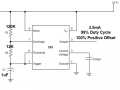
The 555 timer creates 10Hz frequency. My problem now is making the output 100% positive offset, setting it to 3.5mA current with 10 Hz at 99% duty cycle.

Someone told me an OpAmp can set a positive offset on the output pin of the 555 timer. Does this work?

As for 3.5mA, does this change when increasing the voltage of the 555 timer? How can I set the current on the output to stay at 3.5mA without increasing the voltage?
 

Attachments

Last edited:

GopherT

Joined Nov 23, 2012
8,009
Could you draw what you expect from the 555 output and what you need as a signal.
A simple voltage vs time plot. Hand drawn is fine.
 

WBahn

Joined Mar 31, 2012
29,976
You can spec the output voltage or you can spec the output current. In general you can't do both unless you have another part of the circuit that is controlling it to that operating point.

Please be a little more specific about what you want.

For instance: I want the output voltage to be x.xxV 99% of the time and I want it to be y.yyV 1% of the time.

Under what conditions will the output current need to be 3.5mA and what is being driven?
 

jpanhalt

Joined Jan 18, 2008
11,087
Do you you have stable operation at 99% duty cycle? An older application note (AN170) states that the usable range is only up to 95% I would be sure to check that outwith an oscilloscope and not rely on just the calculations. The formula for calculation duty cycle in the LM555 datasheet is:
upload_2015-1-20_1-18-58.png

Where R1 = Ra and R2 = Rb
This online calculator (http://web.udl.es/usuaris/p7806757/555-calculadora/555 Calculator.htm) predicts a duty cycle of 91 to 92%.

John
 

Alec_t

Joined Sep 17, 2013
14,280
1% of a 10Hz signal is a pulse of 1ms duration. So if you really need that resolution you might be better off using one 555 configured as an astable to generate a 10Hz signal of arbitrary duty cycle, use that signal to trigger another 555 configured as a 1ms monostable, and invert the output of the second 555 if necessary (depending on what you intend to drive ).
 

ScottWang

Joined Aug 23, 2012
7,397
If you wish to output 100% duty cycle then you just need a switch switching to output from +Vcc.
When the voltage increasing then you also increasing the resistor that it will keep the current not increasing.
 

WBahn

Joined Mar 31, 2012
29,976
If you wish to output 100% duty cycle then you just need a switch switching to output from +Vcc.
When the voltage increasing then you also increasing the resistor that it will keep the current not increasing.
But he DOESN'T want 100% duty cycle, he wants 99% duty cycle. He wants a 100% offset, whatever that means specifically.

Fuji: A sketch would sure help!
 

ScottWang

Joined Aug 23, 2012
7,397
But he DOESN'T want 100% duty cycle, he wants 99% duty cycle. He wants a 100% offset, whatever that means specifically.

Fuji: A sketch would sure help!
His description wasn't clearly as you said those -- For instance: I want the output voltage to be x.xxV 99% of the time and I want it to be y.yyV 1% of the time.

No specific question there is no correct answer.
 

AnalogKid

Joined Aug 1, 2013
10,986
"100% positive offset sounds like something from a Clark zapper description. The 555 is a unipolar device. That is, it runs on one power supply voltage and ground. So by fizix it can not make a negative output driving a resistive load when viewed on a scope. Fourier analysis of a symmetrical square wave shows that the negative peaks of the fundamental do indeed extend below ground, but I don't know about the behavior of a 99% duty cycle squarewave. So the question to you is this - what do you mean by "100% positive offset"?

ak
 

Thread Starter

Fuji

Joined Nov 8, 2014
100
His silence speaks volumes. ;)
Oh of course, being off and on because I was busy with my family last few days certainly speaks volumes. Volumes of what? Hopefully your not mocking me, because I don't have time for that. Be a little more professional.

Voltage and current is already set to how I want it and the duty cycle is at 99%, so it works on my side. Thanks anyways.

"100% positive offset sounds like something from a Clark zapper description. The 555 is a unipolar device. That is, it runs on one power supply voltage and ground. So by fizix it can not make a negative output driving a resistive load when viewed on a scope. Fourier analysis of a symmetrical square wave shows that the negative peaks of the fundamental do indeed extend below ground, but I don't know about the behavior of a 99% duty cycle squarewave. So the question to you is this - what do you mean by "100% positive offset"?

ak
I need the DC offset just above the center line (which represents the amplitude of 0 on the oscilloscope), just never fluctuation around the center line or touching it 100% of the time, if that is possible.
 
Last edited:

jpanhalt

Joined Jan 18, 2008
11,087
Is your 'scope set to DC or AC signal? As pointed out above, since the 555 doesn't have a negative supply, how can it make a signal below "zero."

John
 

WBahn

Joined Mar 31, 2012
29,976
Oh of course, being off and on because I was busy with my family last few days certainly speaks volumes. Volumes of what? Hopefully your not mocking me, because I don't have time for that. Be a little more professional.
Oh, don't get your knickers in a twist (I think that's the saying). Threads always have a tendency to stray off topic and when the OP stops participating it becomes a bit of open season until and unless they come back (which more often than not they don't -- like most online forums the overwhelming majority of members are "one post wonders").

Voltage and current is already set to how I want it and the duty cycle is at 99%, so it works on my side. Thanks anyways.
Good, glad to hear that.

I need the DC offset just above the center line (which represents the amplitude of 0 on the oscilloscope), just never fluctuation around the center line or touching it 100% of the time, if that is possible.
Now I'm confused. Either is IS possible and you have already done it because you just got done saying that the voltage and current are set how you want it, or it is NOT possible (and/or you haven't accomplished it) in which case the voltage is NOT already set how you want it. Which is it?

It's still a bit hard to tell exactly what you want. A sketch of the voltage versus time, both what you want and what you are currently getting, would sure help.

Are you sure that your scope is DC coupled?
 

ScottWang

Joined Aug 23, 2012
7,397
R1=140K
R2=1.43K
C1=1uF
T1 Output High (Seconds) = 0.09801098999999999
T2 Output Low (Seconds) = 0.0009909899999999998
T Total Period (Seconds) = 0.09900197999999999
Frequency (Hz) = 10.07979840403192
Duty (%High) = 98.99902001959961
 
Top