NE556 doesnt seem interchangeable with LM556

Thread Starter

lasaintlouis

Joined Feb 1, 2017
9
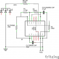
Hi, built this 556 timer-flasher many times with a NE556, always worked. Made this triple one with NE556's and can only get it to flash but not time! Put a LM556 in its place and works perfectly. Never had to do this before, but then put a 0.01uF on #3 and #11 and #4 to Vcc on a NE556 and still doesn't time. What is really weird, I built one 2 weeks ago with LM556 at ends (thought they were NE556) and a NE556 in the middle and they all worked fine, don't get it! I thought NE556 and LM556 were interchangeable.
The main components are the same, pullup resistor 10K, RGB LED, timing resistor 1M, cap 10uF, it must be something very simple I'm over looking but cant figure out what.

G-FLASHER - 8-16-17_pcb.png On a new board, the NE556 only flashes, doesn't time and most importantly doesn't get hot!
Three curious things happen though: 1. doesn't time, 2 keeping trigger constantly low, it constantly flashes but at half the rate for the given cap and R!, 3. voltage between Vcc - #7 timer (#1-556) during constant flashing oscillates between 4.6-5.9v and on the LM556 it is a constant 3.14v (same as the control voltage pin) put a 0.01uF cap on control voltage to GND and #7 oscillates between 3.8-4.1v, control voltage on the NE (which was a constant 3.14, like the LM) now oscillates between 3.0-3.3v!
The LM works perfectly! even without a cap on the control voltage or reset to Vcc.
I realize the simple solution is just use the LM556, but I have used the NE556 as a single timer-flasher many times (without a cap on the control voltage) with no problem. The first board with this sketch and a NE556 in the middle worked perfectly and still does. Replicated it with several different NEs and the NE still doesn't time. Is the NE556 really interchangeable with the LM556?

Les
 

dl324

Joined Mar 30, 2015
18,329
Welcome to AAC!
Is the NE556 really interchangeable with the LM556?
It should be. If you post a schematic, someone can determine which parameters are critical and check specs.

Are these parts from reputable sources and known to be good?

I didn't read the entire post. Your thoughts weren't organized very well and I didn't want to take the time to decipher...
 

Thread Starter

lasaintlouis

Joined Feb 1, 2017
9
sorry for the confusion, will try to be more concise and cogent.

1. built many NE556 single timer-flashers in the past, no problem
2. built three (3) NE556 timer-flashers (circuit above) they don't time
3. use LM556 instead, works perfectly
4. used three (3) different manufactures of NE556 including T.I. still doesn't time
5. put coupling capacitors on the voltage control (never never needed that before) still doesn't time
6. all parts are from reputable companies , digikey, lighthouse, TI.
7. my question is why does the LM556 work and the NE556 doesn't?
 

dl324

Joined Mar 30, 2015
18,329
2. built three (3) NE556 timer-flashers (circuit above) they don't time
What does this mean? Do they trigger, but give unexpected intervals?
4. used three (3) different manufactures of NE556 including T.I. still doesn't time
Who are the manufacturers of the NE556 that don't work? Did you buy them from a reputable source? Do any of the markings look suspicious?
6. all parts are from reputable companies , digikey, lighthouse, TI.
Where did you buy the parts that don't work?
7. my question is why does the LM556 work and the NE556 doesn't?
Need to see a schematic so we can tell which parameters are critical.
 

Thread Starter

lasaintlouis

Joined Feb 1, 2017
9
thanks for your reply. Here is the schematic.
1. have tried putting decoupling caps on the 2 VCs, no help
2. connected reset to Vcc, no help
3. current draw no led lit, 10.7mA
4.current draw led constant, 17mA
5. current draw led flashing, 11-18mA
6. yes it triggers, but flash rate is about half what it is supposed to be for the C & R1, R2
6. NE556-TAIWAN 8436B, TI NE556N General Purpose Dual Bipolar Timer DIP14 (AMAZON) Texas Instruments
 

Attachments

dl324

Joined Mar 30, 2015
18,329
6. yes it triggers, but flash rate is about half what it is supposed to be for the C & R1, R2
So that would make the flash rate about 1.3Hz?

What type of cap is C2 and what is it's tolerance? What is the tolerance of the two resistors?

The LED in the "schematic" is connected backwards. I assume that's a mistake.

Where did you buy the NE556? Can you post a clearly focused picture of the chip showing all of the markings?
 

Thread Starter

lasaintlouis

Joined Feb 1, 2017
9

  • TI NE556N NE556 556 General Purpose Dual Bipolar Timer DIP14 amazon: Business Seller DataAlchemy. Seller Credentials: SBA-Certified HUB Zone Firm, Registered Small Business
  • and from Digi-Key Part Number 296-6504-5-ND
    Manufacturer Texas Instruments Manufacturer Part Number NE556N Description IC OSC TIMER DUAL 100KHZ 14-DIP
  • C2 is a ceramic cap so is C1, used electrolytic caps instead, no difference (both ceramic caps works with a LM556)
  • LED should be common anode, not cathode, my error
  • I have used these same parts, caps, resistors, LEDs on other "single" timer-flashers, works fine.
  • since I'm new to all this (8 months) let's assume I have always unknowingly used a CMOS LM556 and they worked
  • my question is why doesnt a NE556 work? (current draw is about the same, max 18mA)
 

dl324

Joined Mar 30, 2015
18,329
  • TI NE556N NE556 556 General Purpose Dual Bipolar Timer DIP14 amazon: Business Seller DataAlchemy. Seller Credentials: SBA-Certified HUB Zone Firm, Registered Small Business
  • and from Digi-Key Part Number 296-6504-5-ND
    Manufacturer Texas Instruments Manufacturer Part Number NE556N Description IC OSC TIMER DUAL 100KHZ 14-DIP
  • Which is it? Amazon or Digikey? I wouldn't trust any electronic components sold on Amazon. They are not reputable resellers. Digikey is.
  • my question is why doesnt a NE556 work? (current draw is about the same, max 18mA)
They should. The part in question could be bad. You have tried LM556 in this circuit and it works?

Would like a clearly focused picture of the markings on the actual part you're using. If you bought from Amazon, or any other place that isn't known to be reputable, I suspect the part is counterfeit or not known good.
 

dl324

Joined Mar 30, 2015
18,329
built a different timer circuit, NE556 times for only half the R-C time when triggered. The LM556 times correctly
One way to troubleshoot this problem is to monitor the voltage on the timing cap to determine what voltage is causing the timer to change state. This is best done with an oscilloscope, but you could throw together a peak detector to capture that voltage. Numerous schematics should be available on the web.

What is the power source for this circuit and what kind of decoupling do you have on it?

Since the trigger and threshold voltages are ratios of VCC, any variance in the power supply will affect timing.
put decoupling cap to control voltage, then reset to Vcc, no effect on the NE
These aren't absolutely necessary, but are always recommended. A floating reset has little chance of causing an undesired reset, but leaving it opened will make anyone looking at the circuit do a double take. Unconnected inputs are generally considered a poor design practice.

Coupling into the control pin is a more likely problem and can cause erratic timing. So the decoupling cap recommended in the datasheet is usually used to avoid difficult to debug problems. I always include it.
upload_2017-10-1_8-10-2.png
 

Thread Starter

lasaintlouis

Joined Feb 1, 2017
9
1. used digikey NE556, no difference
2. voltage across the timing cap with NE556 is 0.0 since it doesnt time but with constant trigger reaches 4.2V (which is not 2/3 of Vcc). interestingly it takes the RC time to reach that!!
3. used 9v battery and 9v adapter, no difference
4. have previously indicated that i used a decoupling cap with no difference. if not using it can be a problem then why does the LM556 work without it?
 

dl324

Joined Mar 30, 2015
18,329
1. used digikey NE556, no difference
Are you certain of the source of the particular NE556 that doesn't work?
2. voltage across the timing cap with NE556 is 0.0 since it doesnt time but with constant trigger reaches 4.2V (which is not 2/3 of Vcc).
When a capacitor is charged with a voltage source, it will take approximately 1 RC time constant to charge to 2/3Vcc. The exact time is determined by the equation for calculating the voltage on a capacitor:
\( \small V_c = V_i(1-e^{\frac{-t}{RC}}) \)
interestingly it takes the RC time to reach that!!
That indicates a problem. The trigger and threshold levels are set by a resistor divider and the resistors should be matched fairly well. If it's switching at less than 2/3VCC, it would make the timing interval shorter.
3. used 9v battery and 9v adapter, no difference
Do you have decoupling caps on either?
4. have previously indicated that i used a decoupling cap with no difference. if not using it can be a problem then why does the LM556 work without it?
It depends on your definition of working. The datasheets typically recommend putting a decoupling cap on that input to avoid issues with noise being coupled into that pin and giving unpredictable results.
 

dl324

Joined Mar 30, 2015
18,329
voltage across the timing cap with NE556 is 0.0 since it doesnt time
I missed this part. If the timing cap isn't charging, there's a problem. Either the timer is bad or there's a problem with the RC network.

Would you stop saying it "doesn't time" and use a more definitive description? Doesn't trigger, gives incorrect on time, etc.
 

Thread Starter

lasaintlouis

Joined Feb 1, 2017
9
1. Yes certain re: NE556, digikey and texas instruments, this suggests that they are all bad.
2. used this RC network before that is why I was surprised it no longer worked.
3. built a different timer ,above, the NE times for half RC, the LM for RC, no didnt put decoup cap on either
 

dl324

Joined Mar 30, 2015
18,329
1. Yes certain re: NE556, digikey and texas instruments, this suggests that they are all bad.
If all of the parts are from reputable sources, I find it difficult to believe that they're all bad unless you're doing something to damage them or there's something wrong with the circuit.
2. used this RC network before that is why I was surprised it no longer worked.
Those exact components? Or just the same values? Ceramic capacitors are typically 20% tolerance, some closer, some not. It depends on the part. The capacitor tolerance should be marked on the part as a suffix. A cap marked 104M would be a 0.1uF cap with a tolerance of +/- 20%. Your resistors also have a tolerance. If you happened to use a cap that was -20% of it's nominal value and a resistor that was -5% of it's nominal value, the timing interval would be 25% less than what you expected.

That's why I keep asking you to use more descriptive terms to describe the problem. Off by 10%, -20%, 100% vs. "doesn't time".

These are the standard tolerances for AVX ceramic caps:
upload_2017-10-1_10-15-5.png
Kemet uses the same letters. X7R and Z5U caps aren't stable over temperature.
3. built a different timer ,above, the NE times for half RC, the LM for RC, no didnt put decoup cap on either
When you measured the one shot changing state at less than 2/3Vcc on the threshold, how were you measuring the voltage? That type of measurement can't be taken with a DVM because they don't respond quickly enough.
 

Thread Starter

lasaintlouis

Joined Feb 1, 2017
9
1. I realize components have tolerances and have measured the capacitance and resistance with a DVM, the combo wasnt even close to 50% off!
2. dont have a scope but measured voltage on the LM timing cap and got 6.2V as expected.
3. just ordered NE556 directly from Texas Instruments, not Mouser, Digikey or Amazon to side step this idea of fakes.
4. thanks for your input but you and I are spending a lot of time on something that should be obvious but isnt.
5. have built these many times before, one recently last month. I think your suggestion of bad NE556 should be the answer cause nothing else makes sense. I remember buying 10 electro caps once only to find out all but one was shorted, so why not all 30 NE556s are bad!
6. will let you know what happens to the direct T.I. 556

thanks again for everything
Les
 

dl324

Joined Mar 30, 2015
18,329
will let you know what happens to the direct T.I. 556
Next time draw a proper schematic. What you posted is useless for being able to understand circuit operation.

This is what your schematic in post #6 would look like if it was redrawn following typical conventions:
Yours:
G-FLASHER SCHEMATIC_schem.JPG
Mine:
upload_2017-10-1_13-23-38.png
It's easy to see that timer1 is configured as a one shot and timer2 is configered as an astable and that timer1 controls timer2.

It's also more obvious that you don't have any decoupling caps on the control voltage inputs, that one reset is floating, and that the LED is connected backwards.
 

Thread Starter

lasaintlouis

Joined Feb 1, 2017
9
Thanks, btw when I use two 555s instead of a 556 it works fine.
sorry but I thought I already stated that I put decoupling caps and the reset to Vcc to no avail and also that they were not needed on the LM556.
thanks again,
Les
 

dl324

Joined Mar 30, 2015
18,329
sorry but I thought I already stated that I put decoupling caps and the reset to Vcc to no avail and also that they were not needed on the LM556
Yes, I know you said that. But the manufacturers know more than you and they recommend caps on the control pins. Reset not being connected shouldn't cause a problem, but it's a bad design practice to leave inputs unconnected.

This is from a Signetics Application Manual:
upload_2017-10-1_14-3-20.png
The word "monitor" must be a mistake. Something like modulate, alter, or affect would probably be more appropriate.

Nat Semi example circuits all have caps on the control input:
upload_2017-10-1_14-4-57.png
And they state that Reset should not be left floating:
upload_2017-10-1_14-5-24.png

You haven't spent years learning how to design circuits. Those of us who have will take the advice of others who know more.
 
Last edited:
Top