 Facebook
 Google
 GitHub
 Linkedin
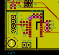
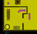
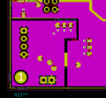
I think I've done everything I can to make my PCB as quiet as possible... I hope. Note that there is a switch mode power supply on the board but far away. Any suggestions/tips for how I can improve the layout? There is nothing on layer 4 bottom in this area. The ADC is measuring a load cell. The lead wires will be maybe 2 inches long.
Also, I'm wondering why this chip is so inexpensive considering a good instrumentation amplifier chip starts at $10. Even with a perfect PCB layout with a perfect input signal and running inside a faraday cage could this chip produce even close to a 24-bit resolution? I'm thinking that a better 16-bit ADC might be worth considering. Thanks.
Also, I'm wondering why this chip is so inexpensive considering a good instrumentation amplifier chip starts at $10. Even with a perfect PCB layout with a perfect input signal and running inside a faraday cage could this chip produce even close to a 24-bit resolution? I'm thinking that a better 16-bit ADC might be worth considering. Thanks.
Attachments
-
 88.9 KB Views: 14
 -
 58.7 KB Views: 11
 -
 63.3 KB Views: 11


