N-Mosfet circuit driving 3-5V flexinol air valve

Thread Starter

swdj25

Joined May 31, 2012
14
Hi,

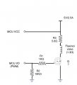
I'm having difficulty driving a flexinol air valve http://www.robotshop.com/en/dynalloy-flexinol-air-valve.html at room pressure (i.e. 1-5psi) and with IRFZ44N Mosfet connected to a PWM pin of 5V Arduino Pro Mini https://www.arduino.cc/en/Main/ArduinoBoardProMini. Here is the schematic with R1 = 1KΩ; R2 = 10KΩ; and R3 = 5.6Ω/5W.
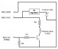
flexinolValve_Arduino_5V_ProMini.jpg

Valve Standard operation:
Voltage: 0.8 to 0.975 Volt
Current: 750 mA
Resistance: 1.3 Ω

Valve performance:
Operating voltage: MIn. 1.6V ON/ Max. 5V
Current draw: 0.8 - 2.5A
PDM frequency: < 5kHz
Flow rate: 3.0 ft3 / min (typical)
Response time: < 0.2 sec ON/OFF


Though the schematics shows that the valve is connected to a pwm pin of the microcontroller, I did test both pwm and digital operations on the software part and they both are not working.

Any suggestion is much appreciated.
s.
 

Alec_t

Joined Sep 17, 2013
15,149
What do you mean by "standard operation" and "performance"? If you are applying only 0.8V to 0.975V to the valve and it needs a minimum of 1.6V it's not surprising it won't work ;).
Is your supply able to provide 2.5A, and with a 3A limit?
The turn-on threshold for a IRFZ44N can be as high as 4V, so a 5V supply may not turn it on fully.
 
Last edited:

Roderick Young

Joined Feb 22, 2015
408
The circuit you have uses a PNP bipolar transistor.

If you want to substitute an n-channel MOSFET, the source should go to ground, the drain to your valve, and +5V supply to the other end of the valve. The IRFZ44N can work driven from an Arduino, but you should just drive it directly - leave out all the resistors in the circuit. The response time of the MOSFET will be slow in electronic terms when driven with only 4.5 to 5 volts at the gate, but should be plenty fast compared to your valve's reaction time of 200 mS. If you plan to do pulse width modulation to control the valve, I'd say go back to either an NPN or PNP transistor instead of MOSFET - that will heat up less when driven in the low kHz range with only 4-5 volts.

Edit: at a later time, you can choose a resistor to put in series with the valve, if desired. Also, your 5 volt supply needs to be hefty to drive this valve, which apparently can take as much as 2.5 amps - that's a lot more than the typical Arduino supply.
 

Thread Starter

swdj25

Joined May 31, 2012
14
@ Alec_t
What do you mean by "standard operation" and "performance"?
I copied the infomation under "standard operation" from the datasheet http://www.robotshop.com/media/files/pdf/electrostem(tm).pdf
and the "performance" form the infomation written on the package.

Is your supply able to provide 2.5A, and with a 3A limit?
The power supply I'm using is an AC-to-DC adapter rated at 5V/2.5A.

The turn-on threshold for a IRFZ44N can be as high as 4V, so a 5V supply may not turn it on fully.
I tested the IRFZ44N in the same schematic with a high voltage LED as load and it worked.
 

Thread Starter

swdj25

Joined May 31, 2012
14
@ Alec_t

I copied the infomation under "standard operation" from the datasheet http://www.robotshop.com/media/files/pdf/electrostem(tm).pdf
and the "performance" form the infomation written on the package. Just now I've got a confirmation by the suypplier that the information on the package is accurate. So here is the valve characteristic:

Operating voltage: MIn. 1.6V ON/ Max. 5V
Current draw: 0.8 - 2.5A
Resistance: 1.3 Ω
PDM frequency: < 5kHz
Flow rate: 3.0 ft3 / min (typical)
Response time: < 0.2 sec ON/OFF

The power supply I'm using is an AC-to-DC adapter rated at 5V/2.5A.


I tested the IRFZ44N in the same schematic with a high voltage LED as load and it worked.
 

Thread Starter

swdj25

Joined May 31, 2012
14
The circuit you have uses a PNP bipolar transistor.

If you want to substitute an n-channel MOSFET, the source should go to ground, the drain to your valve, and +5V supply to the other end of the valve.
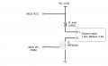
I have made some correction on the schematic with n-channel MOSFET. I have ordered an NPN transistor and will test it soon.
 

Attachments

ScottWang

Joined Aug 23, 2012
7,504
1. You better change to other N mosfet when Rds(on), Vgs=5V, this IRFZ44N, when the Rds(on), the Vgs=10V, it is not good for the uC to drive it.

2. The current limit resistor, the value as R_limit = (5V-(750mA*1.3Ω))/750mA = 5.367Ω
 

Thread Starter

swdj25

Joined May 31, 2012
14
1. You better change to other N mosfet when Rds(on), Vgs=5V, this IRFZ44N, when the Rds(on), the Vgs=10V, it is not good for the uC to drive it.

2. The current limit resistor, the value as R_limit = (5V-(750mA*1.3Ω))/750mA = 5.367Ω
What other N mosfet would you suggest?
I have ordered TIP120 n-channel transistor and will post the feedback soon.
 

ScottWang

Joined Aug 23, 2012
7,504
Here are some n ch mosfet, you can comparing the price and which one you easy to get.

IRL520N_Nch_100V10A_Vgs4V_180mΩ.pdf
IRL530_SiHL530_Nch100V11A_Vgs5V_160mΩ_vish.pdf.pdf
IRL540_Nch_100V28A_Vgs4V_77mΩ.pdf
PSMN017-30PL_Nch30V32A_17mΩ_Logiclevel.pdf
CSD16325Q5C_Nch25V33A_1.7mΩ_Logiclevel.pdf
NTE2987_Nch_100V20A_90Ω_Vgs5V_LogicLevel.pdf
 

Thread Starter

swdj25

Joined May 31, 2012
14
flexinolValve_5vArduinoProMini_MOSFET_noFetResistors.jpg @ Roderick Young

The IRFZ44N can work driven from an Arduino, but you should just drive it directly - leave out all the resistors in the circuit.
I have attached an updated schematic without resistors between the FET gate and the MCU and leave the limit resistor in series with the valve, is it correct?
 

Alec_t

Joined Sep 17, 2013
15,149
That looks ok, provided your FET switches on fully with 5V on the gate. But as far as I can see from the quoted figures, the valve will be only slightly open at 800mA.
 

Roderick Young

Joined Feb 22, 2015
408
View attachment 91643 @ Roderick Young


I have attached an updated schematic without resistors between the FET gate and the MCU and leave the limit resistor in series with the valve, is it correct?
That's what I had in mind. Looking at the curves on the datasheet for the IRFZ44N will work in your circuit with a 5V gate drive. You just don't want to do your pwm at faster than about 1 kHz, or you will be wasting a lot of power in the MOSFET as it slowly turns on. With a 10V gate drive, the transistor will turn on faster, and frequency is less of a concern.

I'm not sure how that valve works. If it's not just a simple open/closed sort of thing, then maybe you're trying to control how far open it is? In that case, I would use NO resistor in series with the valve, and regulate the amount of power going to it with pulse width modulation. You might also need to put a capacitor in parallel with the valve to keep it from chattering.
 

Roderick Young

Joined Feb 22, 2015
408
Yes, it's a nitinol wire but I have no idea what diameter it is.
I see. The main thing is that it's continuously variable, and not an on/off thing like a solenoid. In that case, I'd say definitely leave out the series resistor, and control the amount of valve opening by adjusting the duty cycle of the driving waveform. That will be more efficient, too.
 
Top