N channel mosfet replacement

Thread Starter

Nick Bacon

Joined Nov 7, 2016
130
I currently have 5 x ZVN2110 N channel mosfets used to switch leds on and off. I would like to replace them with an array. I can see that Darlington arrays are readily available, would this be a good replacement.

Currently after lots of mods to the circuit that a couple of the ZVN's are blowing, I am assuming that this is because there are no resistors on the gates to limit current.

The replacement is to tidy up the board design as will as a good saving on cost. So will a NPN array be a good modification?
 

crutschow

Joined Mar 14, 2008
38,484
Yes, you should be able to replace the MOSFETs with Darlington arrays, but not that their output ON voltage is over 1V.
This means the LEDs will have a slightly lower current unless you reduce their series resistor values.

It's unlikely that you MOSFETs are blowing due to a lack of gate resistors since gate current is essentially zero. That's more likely due to voltage spikes on the gates. or overcurrent and overheating from high drain-source current.
 

Thread Starter

Nick Bacon

Joined Nov 7, 2016
130
They were certainly ok when switched off at night, the when powering them up in the morning the MOSFETS are blown, so spikes are likely. Is there a way to stop this? The MOSFETS have a 330mA rating so they are not damaged through load.

Not sure what you mean by the on voltage being over 1v.
 

crutschow

Joined Mar 14, 2008
38,484
They were certainly ok when switched off at night, the when powering them up in the morning the MOSFETS are blown, so spikes are likely. Is there a way to stop this? The MOSFETS have a 330mA rating so they are not damaged through load.

Not sure what you mean by the on voltage being over 1v.
I mean that the Darlington voltage from collector to emitter when on is over a voltage, whereas a MOSFET is typically much less than a volt.
That means there's a volt less to power the LEDs.
 

Thread Starter

Nick Bacon

Joined Nov 7, 2016
130
I am going to work on a schem today for the current setup with all the mods and a possible solution for comments. I think with all the mods I have added to the original circuit, the comparator may be overloaded and it's all getting messy.
 

Thread Starter

Nick Bacon

Joined Nov 7, 2016
130
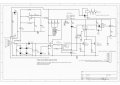
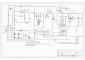
Attached is the schem as things stand now. The basics are that when the circuit detects steam then there is a 12v+ output to pin 7 of TLC3702CP, 0V if detecting water. This output is the basis for the whole led display and relay operation. both the amber led and the red led mosfets are connected to pin 2 of J2. When a jumper is inserted between pin 1 and pin 2 the relay is energised in steam state (when steam is sensed the relay is energised, water sensed, relay de-energised) Pins 2 and 3 jumpered then relay energised in water state (relay energised when water is sensed and de-energised when steam is sensed.

Pin 2 also feed the input signal to operate the relay de-energise delay. There is a 500K pot to adjust the delay. I have noticed that the higher the pot is the more fluffy the relay de-energise action is.

The main concern is the right hand side of the circuit that deals with the leds and the relay.

Attached at the current schematic and the new alternate oneschem.jpg schem-1.jpg
 
Last edited:
Top