Facebook
 Google
 GitHub
 Linkedin
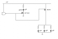
I am not really sure how to describe the issue. Attached is my circuit diagram. Essentially, I have two MOSFET's, one P channel and one N channel that are switched by the output of NAND gate. The N channel mosfet is turned on with +5V logic 1 gate voltage and the P channel is turned on with a logic 0.
Both mosfets are connected to a three wire, common cathode Red/Green LED. With a logic 1, the Green LED is on (powered through the N channel mosfet) and with a logic 0 the P channel mosfet switches on and the N channel mosfet switches off.
This seems to work, but both mosfets are configured as high side and I can see where the N channel mosfet shouldn't work very well because Vgs won't be appropriate. The currents are very small (Maybe 15ma for the N channel Mosfet). On the breadboard this seems to work. But I think maybe I am just lucky!
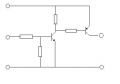
I think the N channel mosfet should be configured low side to the LED load, except I can't see how I might configure one Mosfet high side and one low side while still powering the three wire common cathode LED.
I do have both common cathode and common anode LED's, as well as a two wire Red/Green LEDs that requires the current flow to be reversed for one or the other colour to work.
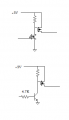
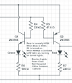
So I am game to any configuration that will switch a single LED from Green to Red based on a changing logic signal. It seems like a very simple thing!
And I am very curious to know if there is a way to connect a common cathode/anode LED to two different MOSFETs in both a high side and low side configuration. I don't think it can be done. But I also don't think I know enough to know that.
Both mosfets are connected to a three wire, common cathode Red/Green LED. With a logic 1, the Green LED is on (powered through the N channel mosfet) and with a logic 0 the P channel mosfet switches on and the N channel mosfet switches off.
This seems to work, but both mosfets are configured as high side and I can see where the N channel mosfet shouldn't work very well because Vgs won't be appropriate. The currents are very small (Maybe 15ma for the N channel Mosfet). On the breadboard this seems to work. But I think maybe I am just lucky!
I think the N channel mosfet should be configured low side to the LED load, except I can't see how I might configure one Mosfet high side and one low side while still powering the three wire common cathode LED.
I do have both common cathode and common anode LED's, as well as a two wire Red/Green LEDs that requires the current flow to be reversed for one or the other colour to work.
So I am game to any configuration that will switch a single LED from Green to Red based on a changing logic signal. It seems like a very simple thing!
And I am very curious to know if there is a way to connect a common cathode/anode LED to two different MOSFETs in both a high side and low side configuration. I don't think it can be done. But I also don't think I know enough to know that.
Attachments
-
29.6 KB Views: 60