 Facebook
 Google
 GitHub
 Linkedin
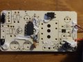
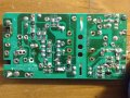
Hi, I opened an older battery charger to see what components could be reused. The transformer in question appears to be part of a pulsed DC flyback converter as it is placed after the full wave rectifier. I would like to reuse this transformer as a low power 120V/60Hz step down transformer for another project drawing no more than 5W.
There are about 40 components so I am going to undertake the challenge of reverse engineering the board though it will take some time. In the meantime, information about the transformer in the photo would be helpful. There are 3 leads on the primary windings and 4 leads on the secondary windings. I suspect one pair of the secondary windings is used for feedback. What about the primary? Also, there appears to be a capacitive dropper in the circuit as all components are present, what's that about? Given the transformer has no markings whatsoever, what can we conclude about it?
As always, thanks for the read.
Attachments
-
 2.3 MB Views: 23
 -
 3 MB Views: 23
 -
 2.4 MB Views: 22


