Hi there.
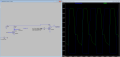
Im developing a PMOS ring oscillator. On the end of this oscillator i've set up an amplifier to convert the oscillating signal to a square wave. This circuit has been simulated in LTspice, as follows:

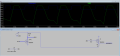
Now in Spice, the square wave switches between 0 and 0.6 volts. Although as you can see below, when i mimic this circuit on a breadboard, i get a square wave which switches between 0 and 4.1 Volts (which is better for my application ofcourse).

Can anyone explain why the difference between the voltages in simulation and in practice is so big?
Thanks in advance!
Im developing a PMOS ring oscillator. On the end of this oscillator i've set up an amplifier to convert the oscillating signal to a square wave. This circuit has been simulated in LTspice, as follows:
Now in Spice, the square wave switches between 0 and 0.6 volts. Although as you can see below, when i mimic this circuit on a breadboard, i get a square wave which switches between 0 and 4.1 Volts (which is better for my application ofcourse).
Can anyone explain why the difference between the voltages in simulation and in practice is so big?
Thanks in advance!
Attachments
-
 176.8 KB Views: 11

 .
.