Facebook
 Google
 GitHub
 Linkedin
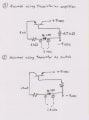
The reason there are two coils (and the same reason why tuning capacitors are usually a ganged pair) is because there are two LC circuits that need to be tuned together.
The first LC circuit is the main RF resonant filter.
The second LC circuit is the local oscillator which is usually set to the AM RF frequency plus 455kHz. When the RF signal is mixed with the local oscillator the result is two signals at the sum and difference frequencies. The difference frequency at 455kHz is called the intermediate frequency (IF) and this is amplified at the IF stage tuned to 455kHz.
That's a quick explanation of how a superheterodyne AM receiver works.

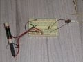
 Though it is not of much practical use, yet, I have been reading up about the subject. This is an enthralling hobby for my (slightly) more mature self now.