Why are you starting yet another thread on this same problem?
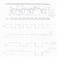
Think about what your waveforms are saying. Q0 changes from LO to HI at clock #2 but nothing else changes. Then it changes back to LO at clock #3 placing everything in the exact same state it was in after clock #1. But then, magically, at clock #4 both Q0 and Q2 change. Does that make sense?
Be methodical about your work. Don't scribble notes on the diagram that are impossible to follow. Make a table that shows the D input values and the state changes for each clock.
Why are you starting yet another thread on this same problem?
Think about what your waveforms are saying. Q0 changes from LO to HI at clock #2 but nothing else changes. Then it changes back to LO at clock #3 placing everything in the exact same state it was in after clock #1. But then, magically, at clock #4 both Q0 and Q2 change. Does that make sense?
Be methodical about your work. Don't scribble notes on the diagram that are impossible to follow. Make a table that shows the D input values and the state changes for each clock.
the question told you the Q output=1 the intentional Q0 (#clk 0 from 1 in waveform) and (#clk 1 from 0 in waveform) ...... the Q1 J0 - K0 => no change ,all the clks 1..... my answer Q0 and Q1 it is true but Q2 and Q3 I don't know true or error!
the question told you the Q output=1 the intentional Q0 (#clk 0 from 1 in waveform) and (#clk 1 from 0 in waveform) ...... the Q1 J0 - K0 => no change ,all the clks 1..... my answer Q0 and Q1 it is true but Q2 and Q3 I don't know true or error!
PLEASE! Just use the normal font. We are all capable of reading and don't need the written equivalent of shouting at us.
Shouting or not, I can't really tell what you are trying to say here. Please rephrase it in more detail. I know we are fighting a language issue, but we can get through that eventually.
My recommendation still holds. Make a table that shows the states of the flip flops and the control inputs prior to each rising clock edge. Or, alternatively, show them as additional traces in your timing diagram.
Several times you have been asked to include the waveforms for the control inputs to the flip flops. That will let us see exactly where you are going wrong so that we can point it out. It's just three signals. But you won't do it. Why not?
It seems like you are just making random changes to your diagram -- and whether you are or not is actually beside the point because, either way, you aren't giving us the information we need to help you effectively.
It's time for you to step up and give the answers to the questions asked of you.
If you don't understand the questions...say so. You won't get points taken off....because no one is grading you and really want to help you succeed. You have to help us help you. No one is a mind reader.
On edit ...
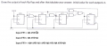
The attachment shows the initial conditions according to your problem statement. Can you fill in each and every location for the FF's with the appropriate signal level?

 Facebook
 Google
 GitHub
 Linkedin


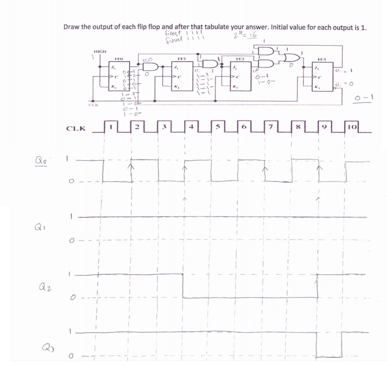


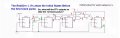


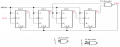
 there isn't answer true#