Multistage Amplifier Design

Thread Starter

israellara331

Joined Sep 21, 2020
6
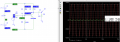
Can someone help me with the designing of a multistage amplifier?
The design specs are:
Minumum of 2 transistors and at least one BJT and one MOSFET
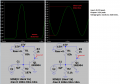
Gain V/V: 25
Rin: 50K Ohms
Rout: Less than 25 Ohms
Power supply: +/-7.5V
Max Swing: Greater than 5 Vpeak to peak
Rload: 100

Much appreciated
 

Thread Starter

israellara331

Joined Sep 21, 2020
6
Multi.PNG
This is my input stage and I'm getting a gain of 56 which is not what I calculated. I am using a 10mV amplitude at the source and a Beta value of 140. Not sure where I am going wrong.
 

Attachments

Papabravo

Joined Feb 24, 2006
21,225
Let's start with the expression for voltage gain in a single common emitter stage. Do you know what the expression looks like?
BTW - it has absolutely NOTHING to do with the Beta of the transistor. This should make sense because beta is a current gain, and we are looking for a voltage gain.
I get a gain of 64.28 based on your circuit values.

Is there some reason why you are operating at such low currents? Your Vbe is only .505 Volts
 
Last edited:

Thread Starter

israellara331

Joined Sep 21, 2020
6
Let's start with the expression for voltage gain in a single common emitter stage. Do you know what the expression looks like?
BTW - it has absolutely NOTHING to do with the Beta of the transistor. This should make sense because beta is a current gain, and we are looking for a voltage gain.
I get a gain of 64.28 based on your circuit values.

Is there some reason why you are operating at such low currents? Your Vbe is only .505 Volts
is it not Avo=-gm* Rc for the common emitter. Is there a different formula when there is an emitter resistor to act as a degeneration for the gain?
 

Thread Starter

israellara331

Joined Sep 21, 2020
6
is it not Avo=-gm* Rc for the common emitter. Is there a different formula when there is an emitter resistor to act as a degeneration for the gain?
Also, should I increase my current to 2ma since I know being in the "micro" range is just on the edge where the current is rapidly changing.
 

Papabravo

Joined Feb 24, 2006
21,225
is it not Avo=-gm* Rc for the common emitter. Is there a different formula when there is an emitter resistor to act as a degeneration for the gain?
It is not correct. The formula involves the collector resistor, the load resistor, the unbypassesd portion of the emitter resistor, and the intrinsic emitter resistor (which is a function of the emitter current).
 

Papabravo

Joined Feb 24, 2006
21,225
Also, should I increase my current to 2ma since I know being in the "micro" range is just on the edge where the current is rapidly changing.
I think an emitter current in that range would produce better results, because it would lower the intrinsic emitter resistance. Then the unbypassed portion of the emitter resistor would allow you to set the gain.
 

Thread Starter

israellara331

Joined Sep 21, 2020
6
I think an emitter current in that range would produce better results, because it would lower the intrinsic emitter resistance. Then the unbypassed portion of the emitter resistor would allow you to set the gain.
So is the gain as follows? -(B*Rc)/(rpi+(B+1)RE) where B is beta, I know you mentioned that it has nothing to do with Beta so I am unsure. I will redo the calculations with a current of 2mA. I'll post the results here later on tonight.
 

Papabravo

Joined Feb 24, 2006
21,225
So is the gain as follows? -(B*Rc)/(rpi+(B+1)RE) where B is beta, I know you mentioned that it has nothing to do with Beta so I am unsure. I will redo the calculations with a current of 2mA. I'll post the results here later on tonight.
You are obviously not looking in the right place. The voltage gain of a CE amplifier involves the ratios of 4 resistances. It is derived by looking at the AC equivalent circuit. The only transistor parameter involved is the intrinsic emitter resistance. We normally approximate it as:
\[ \frac{37 \text {mv}} {I_E} \]

The 37 mv is an approximation to kT/q which ranges from 26 to 52 mV and the emitter current in ma.
As we all know mV/ma has units of....Ω, and that is used to estimate the intrinsic emitter resistance in a CE amplifier.
 

Audioguru again

Joined Oct 21, 2019
6,688
Your attachment has some errors:
1) Your transistor is biased so that it is saturated with extreme distortion.
2) I changed the value of R2 so that the transistor is linear.
3) Since it has no negative feedback then its voltage gain is very high and it has fairly high distortion (the top of the waveform is squashed).
 

Attachments

Top