Multiplex issue, help please!!

Thread Starter

nadjet928

Joined Jan 31, 2019
4
Hi everyone
hope i'm posting this in the right forum section.
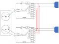
I'm trying to build a ultrasonic anemometer using one hc-sr04 sparkfun version module PCB and 4 ultrasonic speakers (of course i'm using ATMEGA328 for treating the signal) for now i start working with only two speakers, as in the attached pic when each one connected to the multiplex they work but when I add the red conection in addition for me to switch the Transmitter as receiver and receiver as transmitter when i need to, the the output signal of the hc-sr04 become fixed and not effected by anything like putting object in between, or moving them apart.
i'm I using the wrong multiplexers? or the multiplexers not intended to be used as i wanted? any explanation of what is going on here. please and thank you
 

Attachments

Alec_t

Joined Sep 17, 2013
15,112
How much current are you hoping to pass through the multiplexers to the transducers? Those multiplexers are for low currents (a few mA) only.
 

Thread Starter

nadjet928

Joined Jan 31, 2019
4
How did you control the two INH and A,B of two IC?

Have you control them according to their truth table?
Yes I do INH always low AB 00 for channel 0, and 01 for channel, and i'm controlling both IC with same logic level so when first chip AB are 00 same thing goes to second chip
 

Thread Starter

nadjet928

Joined Jan 31, 2019
4
How much current are you hoping to pass through the multiplexers to the transducers? Those multiplexers are for low currents (a few mA) only.
to be Honest with you i didn't measure since the transmitter signal comes from the Micro-controller and the receiver just inputting very low signal
so my assumption was every thing is low current here,
they works fine without the red connection, so the current goes through the chip no over heat or any distortion, once i make the red connection to make them ready to flip roles when i change AB to channel 01 before even change the channel, the signal screwed up.
but you have very good point, I need facts no assumption, so i"ll measure the current check the datasheet and let you know
 

ScottWang

Joined Aug 23, 2012
7,499
Yes I do INH always low AB 00 for channel 0, and 01 for channel, and i'm controlling both IC with same logic level so when first chip AB are 00 same thing goes to second chip
Could you do something as below?
Setup the INH = low, AB = 00H for channel 0, and AB = 01H for channel 1, and to measure the voltages of in/out pins,

and then setup the INH = low, AB = 01H for channel 0, and AB = 00H for channel 1, and to measure the voltages of in/out pins.
 

Thread Starter

nadjet928

Joined Jan 31, 2019
4
Could you do something as below?
Setup the INH = low, AB = 00H for channel 0, and AB = 01H for channel 1, and to measure the voltages of in/out pins,

and then setup the INH = low, AB = 01H for channel 0, and AB = 00H for channel 1, and to measure the voltages of in/out pins.
just to confirm you want me to set INH = low, AB = 01H for channel 0 on the receiver Multiplex IC, and AB = 01H for channel 1 on the transmitter Multiplex IC? wouldn't that short the receiver to transmitter while it's connected as in the picture?
do you want me to do this test while the whole circuit connected or with no ultrasonics?
 

ScottWang

Joined Aug 23, 2012
7,499
just to confirm you want me to set INH = low, AB = 01H for channel 0 on the receiver Multiplex IC, and AB = 01H for channel 1 on the transmitter Multiplex IC? wouldn't that short the receiver to transmitter while it's connected as in the picture?
do you want me to do this test while the whole circuit connected or with no ultrasonics?
Sorry, because the components on right side didn't label as 0 and 1, a little hard to describe, so I followed your description.

1. Setup the first CD4052 as AB = 00H, setup the second CD4052 as AB = 00H and measure their voltage of In/Out pins.

2. Setup the first CD4052 as AB = 01H, setup the second CD4052 as AB = 01H and measure their voltage of In/Out pins.

3. You also measure the voltage of In/Out that disconnect the red lines in the circuit.

Is that right and clear?
 
Top