Facebook
 Google
 GitHub
 Linkedin
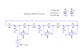
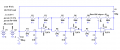
See the attached.
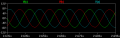
Most values needed to be changed in order to get a halfway decent looking sine wave at the lower frequency.
As shown, the three-phase output will be in the vicinity of 500Hz. To get higher frequencies, decrease C1 through C3. 4.7uF will give you around 900Hz. All three capacitors must have the same value, or you will not get 120° between the phases.
The voltage reference was changed from a pot to a TL431, which is a shunt regulator aka "adjustable Zener". Wired as shown, a TL431 will have a nominal 2.5v from cathode to anode. A 10uF cap is required to keep the TL431 in the stable region.
If you don't happen to have a TL431, you could use a regulator such as an LM317 wired to output 2.5v.
Vcc is 6.5v; this is because the opamp used cannot reach to the positive supply rail, and you need 0v-5v out. This circuit will output from around 100mV to about 4.8v. If you increase Vcc to 6.7v, it should reach 5v with a light load on the output of the opamps.
I don't know what you are planning on driving with this circuit. However, if you put a low-impedance load (below around 10k Ohms) on any of the outputs, it will stop oscillating.
If you want to drive something that has a lower input impedance, you will need to buffer the outputs. You can create a high-impedance voltage follower by using an opamp with it's output wired to the inverting input, and the input signal to the noninverting input. The output will be a mirror of the input signal, but with more current drive capability.
Well... What should I do to the circuit to make sure the output voltage will be in the range of 0V to 20V.... And also, where do I add any indicator to show the failure of respective phases in case there is any
short circuit occurs in any of the phases? Thanks for that... =)