multiple phase sine generator

Thread Starter

traitorousdevil

Joined May 24, 2010
15
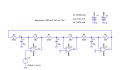
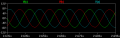
See the attached.

Most values needed to be changed in order to get a halfway decent looking sine wave at the lower frequency.

As shown, the three-phase output will be in the vicinity of 500Hz. To get higher frequencies, decrease C1 through C3. 4.7uF will give you around 900Hz. All three capacitors must have the same value, or you will not get 120° between the phases.

The voltage reference was changed from a pot to a TL431, which is a shunt regulator aka "adjustable Zener". Wired as shown, a TL431 will have a nominal 2.5v from cathode to anode. A 10uF cap is required to keep the TL431 in the stable region.

If you don't happen to have a TL431, you could use a regulator such as an LM317 wired to output 2.5v.

Vcc is 6.5v; this is because the opamp used cannot reach to the positive supply rail, and you need 0v-5v out. This circuit will output from around 100mV to about 4.8v. If you increase Vcc to 6.7v, it should reach 5v with a light load on the output of the opamps.

I don't know what you are planning on driving with this circuit. However, if you put a low-impedance load (below around 10k Ohms) on any of the outputs, it will stop oscillating.

If you want to drive something that has a lower input impedance, you will need to buffer the outputs. You can create a high-impedance voltage follower by using an opamp with it's output wired to the inverting input, and the input signal to the noninverting input. The output will be a mirror of the input signal, but with more current drive capability.

Well... What should I do to the circuit to make sure the output voltage will be in the range of 0V to 20V.... And also, where do I add any indicator to show the failure of respective phases in case there is any
short circuit occurs in any of the phases? Thanks for that... =)
 

SgtWookie

Joined Jul 17, 2007
22,230
You're talking about this circuit, I presume:


As shown, the supply voltage is 6.5v. If you needed other output voltages, you would need to change the supply voltage.

It won't produce true sine waves due to clipping. It's difficult to change the frequency. It is not a particularly wonderful circuit.

The LM324 is an old and slow opamp. I used it simply because they are commonly available; even Radio Shack stores sell them.

I suppose that an indication of operation could be implemented using three LEDs, current limiting resistors, and voltage followers to show that there are outputs from the three phases; they should all glow at about the same intensity. If there is a fault anywhere in the circuit, the feedback path would be eliminated, and it would stop oscillating - only one or two of the LEDs would be illuminated.
 

Thread Starter

traitorousdevil

Joined May 24, 2010
15
Thanks "beenthere"...

Ermz... Rather than LM324, any suggestion for the ap-amp 2 produce 0-20v output from 230v input voltage with 50Hz frequency?
Actually I totally don't have any ideas with the 3 phase sine wave generator... what the lecturer want from us is the "Single Phase to 3 Phase Stimulator"... And I found your circuit there seems quite suitable, so trying used with it... Without actually understanding... >.<
So... Ermz... Could you please help to design a circuit...?
Here the requirement...:
1.The simulated 3-phase voltage supply has the wave shape, frequency and phase differences of an actual 3-phase voltage supply.
2.0V to 20V user adjustable voltage amplitude.
3.There should be indicators to show the failure of respective phases in case there is any short circuit occurs in any of the phases.
4.Optimum load voltage regulation.
Thanks..=)
 

SgtWookie

Joined Jul 17, 2007
22,230
So, this is a homework assignment.

We cannot do your homework for you, as you would only learn how to get other people to do it for you.

The circuit does have an element that you need, which is 120° between the output phases. However, your assignment is different, as the synchronizing input is from an existing source.

You might start by investigating "ring oscillator" circuits, as that is what the circuit I posted is; a form of a ring oscillator.
 

Ron H

Joined Apr 14, 2005
7,063
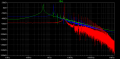
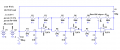
I suspected that this oscillator is dependent on the gain-bandwidth product (GBW) of the op amp, so I ran a sim. It appears that the frequency is proportional to the square root of the GBW, all other factors being equal. I don't have any inclination, right now anyway, to try to verify this mathematically.
The voltage source on the 1st op amp helps get the oscillation started.
 

Attachments

Thread Starter

traitorousdevil

Joined May 24, 2010
15
So, this is a homework assignment.

We cannot do your homework for you, as you would only learn how to get other people to do it for you.

The circuit does have an element that you need, which is 120° between the output phases. However, your assignment is different, as the synchronizing input is from an existing source.

You might start by investigating "ring oscillator" circuits, as that is what the circuit I posted is; a form of a ring oscillator.
Guy... Please.... I totally have no idea with it... The leturer haven't taught us any about the oscillator yet... Asking us to design without teaching... What can i do without understanding... >.<
Please.... >.<
 

beenthere

Joined Apr 20, 2004
15,819
Google becomes a great research and learning tool. For instance, "ring oscillator" brings up 282,000 hits.

If you encounter unfamiliar terms while reading about ring oscillators, use Google to get references for them.
 

Thread Starter

traitorousdevil

Joined May 24, 2010
15
Guys... I totally have no ideas... >.<
Next week would be the date end...
Any more hints please....
Which Op-amp I should use?
What I get right now just if according to #3's circuit,
I am able to get the 120 degree phase shift...
However, the op-amp there, LM324, does not suit to me as I have high input voltage and wish to generate higher output voltage too compare with the circuit...
So, what I think here is, maybe I can replace other op-amp that can generate higher output voltage...
The next problem is the frequency... In that circuit, what actually affect the frequency? I still can't get it...
Well, in conclusion... Is that I'm trying use the circuit in #3 to transform into what I needed is a correct choice?
Please... Give some hints... >.<
 

JoeJester

Joined Apr 26, 2005
4,390
To the OP ...

Are you paying, or your parents are paying, for this education?

If you are paying, then you are not getting your money's worth in this deal.
 
Top