Motorcycle Highbeam-triggered Arduino Garage Opener Remote - General issues

Thread Starter

mvs90

Joined Mar 20, 2012
24
Can you post an image of your "pulses"?
Can you look at the output with an oscilloscope?
Ok, so after a soldering session making some headphone cables, I got around to bringing out the oscilloscope. So it looks like a dropdown resistor wouldn't really be needed, and that the buck converter is coping good enough. While there is a "start up time", it isn't really relevant compared to the time it takes to press the button in the first place. That is, it would be humanly impossible for me to press and release the button before the buck converter reached equilibrium.
 

Thread Starter

mvs90

Joined Mar 20, 2012
24
Oops, I was editing the message and reached the time out.

Can you post an image of your "pulses"?
Can you look at the output with an oscilloscope?
Ok, so after a soldering session making some headphone cables, I got around to bringing out the oscilloscope. So it looks like a dropdown resistor wouldn't really be needed, and that the buck converter is coping good enough. While there is a "start up time", it isn't really relevant compared to the time it takes to press the button in the first place. That is, it would be humanly impossible for me to press and release the button before the buck converter reached equilibrium.

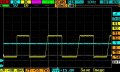
Button Presses -50ms.jpg
(Yellow is the button press @ around 3v, and Blue is 12v constant input)

So there are the button presses. So it looks like the presses are shorter than I thought, but still being quick they are no less than 50-75ms, and around 100ms on average during normal use.

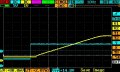
Rising Edge - 10ms.jpg Rising Edge - 2ms.jpg
(Blue is the signal at the output of a push switch which powers the buck converter. Yellow is the output of the Buck Converter)

So it takes about 15ms for the buck converter to rise to a stable voltage. I think that would be perfectly acceptable for an application like this. It would have to be around double to start worrying I'd say.

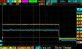
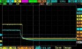
Falling Edge - 10ms.jpg Falling Edge - 2ms.jpg
(Blue is the signal at the output of a push switch which powers the buck converter. Yellow is the output of the Buck Converter)

And a negligible amount of time for it to return to 0. No complaints.

So that's that. Pity I removed the LED's from the Arudino too soon. That's really all I need to see if it's working, and if it's correctly sending power to the remote. Guess I'll replace it next week, double check the remote is working, and by then this should be all set.
 

spinnaker

Joined Oct 29, 2009
7,830
I am seeing no huge transients (not that they aren't happening. I think a better way to do this would be a comparator. The LM393 has an input range of 2-36V. Your output is going to be any level you choose. The advantage is that it will eliminate any noise below the reference voltage and you will get a nice square output.
You should consider it.

Though I do find it really interesting tha tit look like the buck regulator is squaring up your pulse for you.


I am not familiar with the Arduino. Does it (and would be surprised it doesn't) have an external interrupt pin? Are you using it?

FYI you don't need LEDs. Just use your scope. And I am sure the Arduino has a debugger. You could even write another really simple program that sees the input then an output changes pin. Use your scope to watch the change on both the input and test output pin.
 

Thread Starter

mvs90

Joined Mar 20, 2012
24
I am seeing no huge transients
Currently, it's still on the bench BTW. It will eventually be buried under the bodywork in an awkward location, so I am not installing it just yet if it's not working. So I wouldn't be worried about transients until the device has to deal with engine starting-stopping, the charging system, jump starts, etc. Regarding the comparator, ironically the issue is so many choices rather than not enough. That would probably work great. Although still if I had to do the project again I'm unsure if I would make it simpler with resistors or more complex with something like that.

I'm curious if the digital pin being detected at 1 when the voltage is still at around 2 will cause issues, but for that the input voltage would probably have to be at 3-6v or somewhere around there which I doubt would be possible in any significant way connected to the headlight.

I am not familiar with the Arduino. Does it (and would be surprised it doesn't) have an external interrupt pin? Are you using it?
Honestly, I'm not familiar with that nor have I ever used it. I learn as I need, and this is my first practical Arduino project (I'm considering a programmable 2 speed configurable pool timer next if this goes well, although I've already got the parts to just pull it off with industrial timers). I've just taken a look at it and got an idea of what it is, and I probably should have used that but I just wasn't familiar enough with the concept. It would have been nice to shutoff the Arduino when on standby using that, albeit not anything noticeable in real use.

FYI you don't need LEDs. Just use your scope.
I know :( It's just that it would have simplified things since the leds were already there. This is just another things to do on the to do list, and I already reached the frustration and f*** it part. I need that little stamina boost that having the thing work gives.

BTW, thanks for all the input Spinnaker!

If anyone has any reason to think that the buck converter for the headlight signal is not viable for some reason, now would be the time... If not I think that's good enough confirmation that it should work adequately if nothing else.

If this ends well (and it should) it certainly would make a nice DIY. Since it's likely someone down the road is going to find this on Google and want to do the project, I'm attaching the Arduino code, in both normal Arduino and Arduino Trinket versions. Hopefully it can help someone some time from now. The code was working perfectly the last time I tested, and regardless is fully commented should anyone want to change anything.
 

Attachments

Last edited:

djsfantasi

Joined Apr 11, 2010
9,237
The Arduino and Mega have multiple pins which can be used for interrupts. but the TS is apparently using a Trinket - a small member of the Arduino family. Not so sure about its capabilities as it had only a few IO pins in total. Let me look or you can.

Ok, I checked on the Adafruit site (they make the Trinket) and it appears that PB2/GPIO2 is the sole external interrupt available on the device.
 
Last edited:

spinnaker

Joined Oct 29, 2009
7,830
Read up on external interrupt on the Arduino. Your whole problem might simply be you are not catching the event. A properly set up interrupt handler will make it a lot easier to manage. Your code could be busy doing other things and your handler will still catch the event.

Nothing wrong with polling, as you are probably doing and it tends to work fine with longer events as your scope images appear to show but you still might benefit from interrupts plus it will be a good education.
 

Thread Starter

mvs90

Joined Mar 20, 2012
24
I definitely think interrupts are worth learning, and for a more complex project it is a must. But in this case where a barebones Arduino was used, and the 99.9% of the time the chip has nothing to do but wait for a high pin, I think an interrupt would only be worth it in this project if I were to put the chip into sleep state when not needed, and that was too much to get into for my first microcontroller project. Now if the micro had simultaneous things to do, that would be a whole different story.

But it's great to hear those suggestions for future projects of course.

In case it isn't clear, the Arduino + garage remote was working perfectly connected to a power supply and on a breadboard. It was powering the remote, and opening the garage when the button sequence was detected flawlessly. The only new components are the buck converters and that it was assembled and soldered. And as of now it doesn't work. Solddering looks fine, so either (unlikely) heat damage, plain bad luck, or the remote loosing configuration. I feel relatively confident with the buck converters, so now it's down to whats been said. Testing the arduino and remote separately. Regrettably, the micro usb on the arduino isn't properly accesible since it's got double sided tape to the PCB. I tried connecting it to a PC but couldn't get a connection in order to load some test code. Might have to mill a usb plug to fit. I guess there isn't anything else to do until I test those things.
 

spinnaker

Joined Oct 29, 2009
7,830
IMHO the 5v Buck is the wrong way yo go to limit the pulse voltage. I better way might be a zener or a comparator. If you are concerned about transients then you are mistaken if you think the regulator is going to protect your input. A good spike is going to take that regulator right out. Working with automotive circuits is an art form on to its own.

What I would do is to create a new thread. Forget about the Arduino or all of the other details of the purpose etc. Just mention the pulse for now. Boil your requirements down into just a few sentences. Do be sure to mention the source of the signal. The fact it is on a motorcycle is very important. Do include your scope measurements.

Here is a sample of a problem I had where I used a comparator to solve the problem. I had the opposite issue as you, my input signal was not high enough. I modified my LTSpice model to make it a little closer to yours in that the input signal is 0 to 12V. The green line is input. The blue output. You can see how I now have 0-5V with a nice crsisp square wave and no noise.

upload_2017-2-5_13-34-39.png


This is an inverting comparartor configuration but you can easily change it to non inverting.

upload_2017-2-5_13-37-38.png
 

Thread Starter

mvs90

Joined Mar 20, 2012
24
IMHO the 5v Buck is the wrong way yo go to limit the pulse voltage. I better way might be a zener or a comparator. If you are concerned about transients then you are mistaken if you think the regulator is going to protect your input. A good spike is going to take that regulator right out. Working with automotive circuits is an art form on to its own.
Your definitely right about automotive circuits being an art form. That's the crux of the issue. Thanks for the images. I'm going to look at them later and the comparator to consider my options.

As of now, I just unsoldered the Arduino and testing so far shows it's dead. No output voltage and not being detected by the PC. Not sure what happened to it but at least that's confirmed.

I also just got back after writing the last sentence. I just tested the garage remote. It works. So the whole issue was the Arduino chip gone bad. I guess I'll replace it next week and try again. I have until then to decide about changing out the signal buck converter. I'm almost more inclined towards using a Zener diode (plus I already have those in stock), though I've never used them for anything practical so I'm not completely sure how I'd approach it, or the advantages of doing so. I don't think a perfect square wave is crucial to this project, but the spike resilience does sound worth it.

BTW, one thing that puts me off about the comparator is having to create another reference voltage to compare the input with (as well as another potential failure point to protect), and adding more components that may or may not fit easily inside of the remote housing. The way it's set up now I get straight 3.3v at the output of the buck converter in a single package without any more components to juggle. If anything fails, at least now I know exactly what it is, and replacement is quick without disturbing the rest.

Another note, after reviewing interrupts I don't think it would suit this project. For two reasons. The first, interrupts are great when you need to interrupt the main code to do something else. Since the main code is looking for the signal, an interrupt really doesn't provide any benefit. This project is "too simple" for that. The other is that millis() doesn't behave well when using interrupts, and the code makes extensive use of millis(). It would create more problems than it would solve in other words.
 
Last edited:

Thread Starter

mvs90

Joined Mar 20, 2012
24
So I've kept looking at this. More random issues.

Would anyone know why in the world a garage opener would work when powered by a button battery, but absolutely not work when powered by either of two power supplies set to the same voltage? If I hadn't had checked it multiple times, I wouldn't believe it. I can't justify it myself, and if someone told me this I'd say they are doing something wrong. I'll probably try another unit of the remote since before it did work like this, but it's bugging me.

So after so much back and forth about the buck converters, I'm just about ready to drop that idea and go with automotive LDO regulators which are designed with nasty automotive inputs in mind. I'm looking at the Texas Instruments LM2931 and LM2937. Kind of depends on what fits in the enclosure. I'll probably go with the 5v version to power the Arduino, and the same 5v plus voltage divider to convert the signal. In this application, I 'd like to think that dropping the capacitors would most likely have no affect. That way hopefully it would all fit, and I could have this over with sooner rather than later.
 
Last edited:

spinnaker

Joined Oct 29, 2009
7,830
IMHO you are just really lucky the pulse worked through the buck regulator. It really isn't designed to be used in that way. In actual use you would have likely seemed similar behavior. One time it would work the next time not.
 

Thread Starter

mvs90

Joined Mar 20, 2012
24
IMHO you are just really lucky the pulse worked through the buck regulator. It really isn't designed to be used in that way. In actual use you would have likely seemed similar behavior. One time it would work the next time not.
My issue with the buck regulator is more that it's a cheap Ebay part where the output voltage is too easy to bump out of adjustment, and isn't behaving well with my power supply (Tattoo machine power supply). If it were fixed output, I'm not sure there would be an issue. Although there are plenty of bugs in this project for the moment so who knows.

Do you think an automotive LDO Regulator designed for direct connection to a car battery would be okay? As the power supply I'm sure (although if I don't install the capacitors due to space restrictions, I'm unsure of the consequences), but to convert the voltage of the signal I'm not so convinced. Perhaps I'll install one automotive regulator, and use that to power both the arduino and an optocoupler (4N25), but I'm unsure how viable that is space wise.

If someone can provide some guidance on how essential the capacitors for the regulators are, that would be nice.

If I was willing to not install it all inside the remote housing, I could also simply use a relay for the headlight signal with that bridging the 3.3v output of the arduino to the signal input, and the regulator to power the Arduino. The options are overwhelming. Especially when so much emphasis in "doing it right" is put in a non-critical circuit that only costs around 20 bucks.

Part of me really just wants to hook the Arduino up to the 12v battery directly, and use a voltage divider for the signal input like other people have done and call it a day.
 
Top