Motorcycle Highbeam-triggered Arduino Garage Opener Remote - General issues

Thread Starter

mvs90

Joined Mar 20, 2012
24
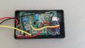
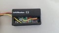
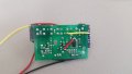
2017-02-04 12.12.54.jpg 2017-02-04 12.13.15.jpg 2017-02-04 12.11.42.jpg

Hi there,

So, inspired by this DIY, what was supposed to save me a few seconds a day turned into me finally learning Arduino and countless hours spent in issues completely unrelated to the initial project (including a cute little robot tank). Never completely finished the opener though, and now I'm trying to get it done.

First, some context. It's an Arduino controlled (Adafruit Trinket 3.3v) garage opener remote (Liftmaster 371LM - Runs on 3v) for a motorcycle.

The Arduino programming has been taken care of, with the debouncing being the most complicated part because I overengineered that a bit since simpler methods weren't working. The current programming makes "Press, Press, Hold" of the passing headlight button (momentary switch) within 3 seconds activate the garage opener for half a second. "Press, Press, Press, Press, Hold" within 5 seconds keeps the remote permanently activated (until button release) for remote programming.

The "device" would have 3 cables - 12v on ignition, Ground, and Headlight signal (12v). The complicated parts was an efficient way to turn those 12v to 3v in the electronics-hostile automotive environment (with unlikely, but potentially huge reverse voltages and voltage spikes). I ended up going the easy way with 2 buck converters (one for 12v to power the Arduino and remote, and one to "translate" the effectively digital signal of the headlight turning on). They at least provide quite a bit of leeway with input voltage, and are cheap to replace if damaged. Plus, everything is so compact that it should all fit inside the original remote housing.

I got it working on a bench setup (without the buck converter, simply running on batteries), but weeks later when I finally soldered the working part, it didn't work. Since I removed the LEDs from the Arduino (for energy efficiency), troubleshooting has been hard. One buck converter was fried (never really sure why), so at this point I'm not sure that either the Arduino or Remote work without further testing. Garage door openers can be finnicky as is, so all this is only making it worse.

I'd be happy to provide more info or code if somebody wants it, but for now I just had a question or two.

1. Would a buck converter be suitable for providing a digital signal (12v of headlight to 3v). I only need to know if it's on or off, and given the .2 seconds more or less it takes for a button press, it would have to do so quickly.

2. Once installed, I assume the headlight itself would work as a pull-down resistor, but out of the installation I'm not sure if I should add a resistor to drain the voltage out of the buck converter for the headlight signal for quicker response (or just to get it to work at all). It's one of the things that I'm suspicious about for it not working now.

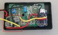
3. BTW, does anyone recognize the antenna in the pictures of the remote? I suspect it's the shortish bare wire bridge, but it isn't really obvious to me.

If someone could give me some tips on that, I'd probably have more questions. Right now I'm just a bit stressed with putting so much time to just shave a couple of seconds looking for a remote. I was hoping this whole thing would be easier honestly. Probably would be if I just used resistors, but it didn't really feel like the right thing to do.
 
Last edited:

crutschow

Joined Mar 14, 2008
38,668
1. Would a buck converter be suitable for providing a digital signal (12v of headlight to 3v). I only need to know if it's on or off, and given the .2 seconds more or less it takes for a button press, it would have to do so quickly.
For a 3V digital signal from the 12V headlight (15V max. when running), all you need are two resistors as a voltage divider, such as 40kΩ to the headlight and 10kΩ to ground.
To avoid false triggering, you can place a small capacitor (10μF or so) from the micro input (voltage divider output) to common.
You only need a buck converter if you require significant power.
2. Once installed, I assume the headlight itself would work as a pull-down resistor, but out of the installation I'm not sure if I should add a resistor to drain the voltage out of the buck converter for the headlight signal for quicker response (or just to get it to work at all). It's one of the things that I'm suspicious about for it not working now.
The resistor divider will act as a pull-down.
3. BTW, does anyone recognize the antenna in the pictures of the remote? I suspect it's the shortish bare wire bridge, but it isn't really obvious to me.
Yes, the remote antenna is generally a short piece of wire or even no wire.
Just the radiation from the circuit or a PCB trace may be sufficient.
 

Thread Starter

mvs90

Joined Mar 20, 2012
24
Thanks for the answer.

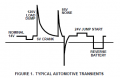
I considered the voltage divider, however given that 120v spikes in automotive environments are something worth taking into account.

nHgG3.png

Even components like optoisolators are recommended for a simple application like this, but I think that's definitely over complicating. I considered a voltage divider, 4N25 Optoisolators, high value resistors with zener diode, just a zenner diode, and other resistor configurations and eventually went with the buck converter as a compromise. I'd want as close to 0 current draw during standby, and a compact (simple) footprint as priorities. But it might be worth it to simply take the risk with the voltage dividers and see if that works in the long term.

Though the question still stands if buck converters are an acceptable solution to begin with, since that's whats already been soldered. Unless it's not a good idea, I wouldn't want to change it for no reason.
 

spinnaker

Joined Oct 29, 2009
7,830
For a 3V digital signal from the 12V headlight (15V max. when running), all you need are two resistors as a voltage divider, such as 40kΩ to the headlight and 10kΩ to ground.
To avoid false triggering, you can place a small capacitor (10μF or so) from the micro input (voltage divider output) to common.
You only need a buck converter if you require significant power.
The resistor divider will act as a pull-down.
.
Keeping in mind that the reduction in voltage will be through heat (i.e. energy loss) but assuming the charging circuit on your motorcycle is functioning correctly, the loss will not be worth worrying about and the divider a far easier way to go than a buck converter.

Speaking of charging circuits, from my memory the charging systems in motorcycles are typically very noisy. How would the TS deal with that?
 

Thread Starter

mvs90

Joined Mar 20, 2012
24
from my memory the charging systems in motorcycles are typically very noisy. How would the TS deal with that?
TS? Not familiar with that abbreviation. Regardless, I don't think it would be able to ultimately trigger the garage opener since the sequence is pretty specific (Press, Press, Hold - Within 3 seconds, and with no more than a second between pushes. If the sequence is wrong, the it won't accept an input for 5 seconds). It would be irrelevant if it momentarily detects a high beam pulse since it wouldn't be enough to trigger anything, and code is already setup with a cool down timeout so I can't see it ever causing an issue I would ever notice.

far easier way to go than a buck converter
But is a buck converter viable? Given that the buck converter is already installed, it's easier to just use that then start over. I did take for granted that the buck converter would deal with transients way better than the voltage divider, which is something answers to other users on similar projects made me concerned with.
 

spinnaker

Joined Oct 29, 2009
7,830
Though the question still stands if buck converters are an acceptable solution to begin with, since that's whats already been soldered. Unless it's not a good idea, I wouldn't want to change it for no reason.


Certain buck regulators are rated for automotive use. At the very least you would probably want one of these. But I am thinking you might want to have more protection that that. Perhaps someone more experienced in noisy circuits could weigh in. Do you have a power port on your motorcycle to plug in devices (like in an automobile)? It might already have sufficient protection.
 

crutschow

Joined Mar 14, 2008
38,668
My answer was for a digital signal for the headlight flashing signal, not for powering the micro.
The buck converter is fine for powering the micro.

Don't understand you concern about current draw, since the circuit should be unpowered when the engine is off.
 

spinnaker

Joined Oct 29, 2009
7,830
TS? Not familiar with that abbreviation. Regardless, I don't think it would be able to ultimately trigger the garage opener since the sequence is pretty specific (Press, Press, Hold - Within 3 seconds, and with no more than a second between pushes. If the sequence is wrong, the it won't accept an input for 5 seconds). It would be irrelevant if it momentarily detects a high beam pulse since it wouldn't be enough to trigger anything, and code is already setup with a cool down timeout so I can't see it ever causing an issue I would ever notice.
.
TS = Thread Starter. It used to be OP = Original Post. Don't ask me why they changed it.

I would not be too concerned about a false trigger. What I wold be concerned about is it not triggering when you want. If it is intermittent and you don't care then probbaly not a big deal. Frankly my store bought remote does not trigger from time to time and I have yet to figure out what is going on.
 

Thread Starter

mvs90

Joined Mar 20, 2012
24
But noise aside, would a buck converter be feasible to begin with to detect 200ms button pulses? Should I be adding a drop-down resistor on the output side of the output of the buck converter before the arduino pin inputs?

Just for some context at this point, how the system works is that one buck converter provides power to the Arduino as soon as the vehicle is powered on. If the bike is started with the headlights on, the remote is never powered. Once the headlights turn off, there is a brief timeout. After the timeout it waits for headlight on. As soon as it detects the headlight, it powers up the remote (but not triggers) off an Arduino output pin in case the remote is triggered. If the pattern is wrong or the headlight stays on over 3 seconds it powers off and initiates a timeout. If the pattern is right, it will either trigger the remote momentarily or until the headlight button is released. Regardless, after that timeout, everything powers off, and back to standby.

The garage door opener remote consumes about 2.5-3.5mA during operation, 0mA during standby.

TS = Thread Starter. It used to be OP = Original Post. Don't ask me why they changed it.
Thanks! And me looking up electronics abbreviations lol.

What I wold be concerned about is it not triggering when you want. If it is intermittent and you don't care then probbaly not a big deal. Frankly my store bought remote does not trigger from time to time and I have yet to figure out what is going on.
Exactly. That's why I overcomplicated the debounce detection in the code. It's pretty much a sliding scale of button press confidence in which the trigger has to be detected for 10ms more or less consecutively, but does allow for missed ms as long as they are compensated for afterwards. The lack of LED's, or even assurance that the remote didn't get unprogrammed during the DIYing, is one reason that troubleshooting is a bit hard. And the Trinket has no serial display which doesn't make things easier. As of now, I only know that the buck converters are outputting the proper voltage (3v for the trigger, 9v for powering the Arduino).
 

Thread Starter

mvs90

Joined Mar 20, 2012
24
My answer was for a digital signal for the headlight flashing signal, not for powering the micro.
The buck converter is fine for powering the micro.
I imagine the arduino input pin is less delicate to transients, but I suspect the headlight (which is currently a 110w set of high power HID's + devil eye's + angel ring with corresponding ballasts and circuitry) is also capable of ugly voltages. But then again, I suspect I'm spending more time trying to avoid something that probably won't happen, than replacing the component if it ever did happen. I am considering just going with the dividers and that's that. Funnily enough, the whole reason I didn't go with that was all the forum posts recommending against the use of that in an automotive environment when I was doing the research part of the project.
 

crutschow

Joined Mar 14, 2008
38,668
ut noise aside, would a buck converter be feasible to begin with to detect 200ms button pulses? Should I be adding a drop-down resistor on the output side of the output of the buck converter before the arduino pin inputs?
I'm confused. :confused:
If the buck converter is powering the micro, how can it also be used to detect the 200ms pulses?
Are you talking about two buck converters?
 

Thread Starter

mvs90

Joined Mar 20, 2012
24
I'm confused. :confused:
If the buck converter is powering the micro, how can it also be used to detect the 200ms pulses?
Are you talking about two buck converters?
2017-02-04 12.12.54 - Copy.jpg

Yup, two buck converters. One set to 3v (detect pulses), one set to 9v (Power Arduino). Since they are dirt cheap, I had a handful, and can cope with a wide range input voltages while providing a constant output, and would have some internal protection, it seemed like a good all around choice.
 

spinnaker

Joined Oct 29, 2009
7,830
View attachment 119921

Yup, two buck converters. One set to 3v (detect pulses), one set to 9v (Power Arduino). Since they are dirt cheap, I had a handful, and can cope with a wide range input voltages while providing a constant output, and would have some internal protection, it seemed like a good all around choice.

Really nice job of using "off the shelf" solutions.
 

Thread Starter

mvs90

Joined Mar 20, 2012
24
Really nice job of using "off the shelf" solutions.
If only it worked! :mad:

At least from the posts there doesn't seem to be any red flag which is good. There isn't ever a "best" solution, and the worst anyone has said here is that there are simpler options. At this point I'm more inclined to think there was some screwup during assembly or simply a dumb oversight, and not anything inherently wrong with the design. I guess I'll have to take apart, test each component separately, and reassemble. I really shouldn't have left so much time between the prototype on the breadboard and the final assembly...
 

crutschow

Joined Mar 14, 2008
38,668
The buck converter output may not respond fast enough to detect the pulses.
Can you look at the output with an oscilloscope?
 

spinnaker

Joined Oct 29, 2009
7,830
The buck converter output may not respond fast enough to detect the pulses.
Can you look at the output with an oscilloscope?

I think I finally understand what the OP is trying to do with the pulses.


From analog.com regarding startup time of buck regulators.

Start-Up Time: Start-up time is the time between the rising edge of the enable signal and when VOUT reaches 90% of its nominal value. This test is usually performed with VIN applied and the enable pin toggled from off to on. In cases where the enable is connected to VIN, when VIN is toggled from off to on, the start-up time can substantially increase because the control loop takes time to stabilize. Start-up time of a buck regulator is important for applications where the regulator is frequently turned on and off to save power in portable systems.
 

Thread Starter

mvs90

Joined Mar 20, 2012
24
The buck converter output may not respond fast enough to detect the pulses.
Can you look at the output with an oscilloscope?
Yes, and I guess that's one more thing to add to the to do list if each individual component is working properly. I guess it's nice to find some use for the mini oscilloscope I bought some time ago. That's how I measured the average 200ms for a quick button press (which oddly enough I couldn't find a value for online). I had thought about doing that (checking the response of the buck converter output), but it's just getting to the point that the concept of purely saving time and effort with this garage opener is beyond laughable. Oh well, at least there's a cool factor to it I guess.

The ironic part might be that the post that inspire me to do this did it with one or two schottky diodes, and that's it. Never really found out anybody who would corroborate that that's an adequate way to do it though. Seemed like it was taking alot of things for granted.
 

spinnaker

Joined Oct 29, 2009
7,830
Yes, and I guess that's one more thing to add to the to do list if each individual component is working properly. I guess it's nice to find some use for the mini oscilloscope I bought some time ago. That's how I measured the average 200ms for a quick button press (which oddly enough I couldn't find a value for online). I had thought about doing that (checking the response of the buck converter output), but it's just getting to the point that the concept of purely saving time and effort with this garage opener is beyond laughable. Oh well, at least there's a cool factor to it I guess.

The ironic part might be that the post that inspire me to do this did it with one or two schottky diodes, and that's it. Never really found out anybody who would corroborate that that's an adequate way to do it though. Seemed like it was taking alot of things for granted.

Can you post an image of your "pulses"?
 

Thread Starter

mvs90

Joined Mar 20, 2012
24
It's not saving time that's important.
It's the cool way to operate the garage door opener. :cool:
Hearing that alone justified learning Arduino for this project :)

Can you post an image of your "pulses"?
Right now I'm more concerned whether:
a. The remote is properly configured and fully functioning - aka would open the garage with a simple switch
b. If the Arduino is not fried thanks to one of the buck converters failing (The buck converter started to heat up until, I presume, it fried since I couldn't set the output at 1v. But at that point I simply trashed it and installed another one. It should have never been at a voltage capable of damaging the Arduino, but then again, Murphy might have paid a visit)

But now that I think of it, it wouldn't really take that much time to bring out the oscilloscope and simply test as is for reassurance. Will do. Hopefully in the next day or two.

I'm probably going to just duplicate the whole circuit on a breadboard and see whats going on there. Really the important part of this post is motivation, since I was starting to get annoyed at the project and just considering shelving it for the moment. Perhaps I'll try again next week when I receive the replacement parts.
 
Top