Motor Driver Unit Design

Thread Starter

ẞeekay Kunene

Joined Apr 5, 2019
8
Hi

I am doing a third-year design project and I have been assigned to do the motor driver unit part.
Based on the research I made, I founded out that the single-phase stepper motor can be driven in two ways namely VFD and Stator power supply control.
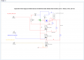
I was able to come across a triac crowbar circuit which gave me an idea to use the voltage divider rule for the system and I designed it on multisim and the simulation worked as expected. I just wanted to find out if it will work before I even test it since this is a dangerous circuit.

I have attached a circuit schematic and the project description pdf file.
 

Attachments

shortbus

Joined Sep 30, 2009
10,045
I founded out that the single-phase stepper motor can be driven in two ways namely VFD and Stator power supply control.
Are you sure that is the type of motor you are working with? The motor mentioned in your schematic is a shaded pole motor not a stepper motor, the two are nothing alike. And neither one of them are controlled with the methods you mention.
 

Thread Starter

ẞeekay Kunene

Joined Apr 5, 2019
8
Are you sure that is the type of motor you are working with? The motor mentioned in your schematic is a shaded pole motor not a stepper motor, the two are nothing alike. And neither one of them are controlled with the methods you mention.
Yes It is a shaded pole motor , I made a mistake . Thanks for replying.

A shaded pole motor can be driven using a circuit such as the light dimmer circuit and control the switching frequency of the triac using pulse width modulation and I made a mistake by assuming that the Triac control method is the same as the VFD.

I will be varying the voltage to the motor using the voltage divider rule which I am not sure if it will work with real components.
 

cmartinez

Joined Jan 17, 2007
8,218
Shaded pole motors can more easily be controlled using a triac, through the phase angle control technique. Although it would definitely work, I suggest you avoid using PWM for this application because it would most likely only complicate things for you. There's plenty of phase angle control circuits out there that you could very easily google up. And as a side note, a shaded pole motor's power can be more or less successfully controlled by varying its voltage, but keep in mind that this type of particular motor needs a very large amount of current to get started, and is a little prone to stalling when the applied voltage is less than the one it was designed to work with.

1.jpg
 

MaxHeadRoom

Joined Jul 18, 2013
28,617
I see you also have to use a temp sensor to control fan rpm, also a digital diplay of rpm, this will require a few extra sensors and electronics.
Is this Homework?
Max.
 

Thread Starter

ẞeekay Kunene

Joined Apr 5, 2019
8
Shaded pole motors can more easily be controlled using a triac, through the phase angle control technique. Although it would definitely work, I suggest you avoid using PWM for this application because it would most likely only complicate things for you. There's plenty of phase angle control circuits out there that you could very easily google up. And as a side note, a shaded pole motor's power can be more or less successfully controlled by varying its voltage, but keep in mind that this type of particular motor needs a very large amount of current to get started, and is a little prone to stalling when the applied voltage is less than the one it was designed to work with.

Thanks for the reply.

So in the case of achieving the three voltages (80V/150V/220V) can I use this circuit with an optoisolator to control it with a digital signal from the speed reference unit ?
 

cmartinez

Joined Jan 17, 2007
8,218
Thanks for the reply.

So in the case of achieving the three voltages (80V/150V/220V) can I use this circuit with an optoisolator to control it with a digital signal from the speed reference unit ?
Yes, you could do that. What is the speed reference unit like? Is it an MCU? What kind of output does it have? Analog/Digital?
 

Thread Starter

ẞeekay Kunene

Joined Apr 5, 2019
8
Yes, you could do that. What is the speed reference unit like? Is it an MCU? What kind of output does it have? Analog/Digital?
3 bits digital signal to 3 optoisolators ,each optoisolator will be turned on by one bit corresponding to it respective driving voltage level, something like the one on the schematic.
 

cmartinez

Joined Jan 17, 2007
8,218
3 bits digital signal to 3 optoisolators ,each optoisolator will be turned on by one bit corresponding to it respective driving voltage level, something like the one on the schematic.
So you want to end up with three different speeds? Or would that be eight different speeds?

EDIT: Pardon me... would that be seven different speeds?
 
Top