Hi Les
i have just done the light test and as per your drawing the lamps light as expected ok.
please can you do a drawing of the motor setup to show switching and motor and i will sort out a temp manual switch.
thanks so much for the help as i have gone cable blind trying.
In post #9 you say that W1 and U1 are linked in the motor. There MUST BE NO CONNECTION BETWEEN THE MAIN AN AUXILIARY windings within the motor.
I have not marked the ends of the winding as I don't know if the lables U1,U2, W1 and W 2 are on the wres from the winding or they are on the teminals. (You have not posted any pictures of the inside of the motor connection box.)
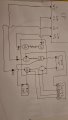
The basic concept is that the polarity for one widing is reversed between forward and reverse but the polarity of the other winding is the same for forward and reverse. The capacitors are in series with the auxilliary winding. Both capacitors are in parallel for starting. Only the run capacitor is connected when the motor is up to speed.
In post #9 you say that W1 and U1 are linked in the motor. There MUST BE NO CONNECTION BETWEEN THE MAIN AN AUXILIARY windings within the motor. View attachment 323095
I have not marked the ends of the winding as I don't know if the lables U1,U2, W1 and W 2 are on the wres from the winding or they are on the teminals. (You have not posted any pictures of the inside of the motor connection box.)
The basic concept is that the polarity for one widing is reversed between forward and reverse but the polarity of the other winding is the same for forward and reverse. The capacitors are in series with the auxilliary winding. Both capacitors are in parallel for starting. Only the run capacitor is connected when the motor is up to speed.
I will be trying this out tomorrow first thing.
Les thank you so much for your time I really do appreciate it.
Kind regards
Mark.
I will give an update once wired up.
I will be trying this out tomorrow first thing.
Les thank you so much for your time I really do appreciate it.
Kind regards
Mark.
I will give an update once wired up.
Hi Les.
Many thanks your a star as your drawing was spot on and i saw my mistake straight away with position of the caps.
It is now working perfect thanks to you.
Kind regards
Mark
the mistake i made was the centrifugal switch when i added it to the same connection of the v1.
i got the red and blue correct but not the white cable which should have gone to U1 or U2 with black being the opposite to the white cable. but all good and working fine so that's all thanks to your help.
 Facebook
 Google
 GitHub
 Linkedin