Motor connection from the treadmill

Thread Starter

olegvm

Joined Dec 26, 2018
10
Good day.

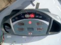
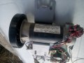
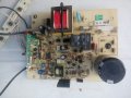
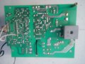
I have a motor from a treadmill and its electronic control.

I want to use this in a wood cutting machine.

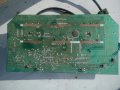
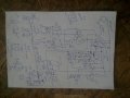
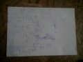
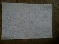
I began to draw a diagram of this electronic control in order to understand how to use it without electronic control of the treadmill.

But I wonder where I can put a variable resistance to regulate the speed of rotation of the motor.

And is there enough engine power and speed for the above purpose. I would also like to know if it is possible to use this engine for rotating a hydraulic pump in a hydraulic station used in a firewood machine.

If this is interesting to someone, then I will post the diagrams and motor data drawn by me.

Sorry for the poor translation of Google my text
 

Thread Starter

olegvm

Joined Dec 26, 2018
10
That is a DIY pic version, I thought you had the original motor board?
Or is that a MC2100 board?
Max.
This is a fragment of the original treadmill motor control circuit.

Do not control the treadmill itself.

There is a very difficult to draw electronic board and I do not need it.

On the presented diagram there are only control signals coming from it.
 

Thread Starter

olegvm

Joined Dec 26, 2018
10
As I understand it, if you do not use the electronic control board for the treadmill, but only the electronic control board for the motor, in order to increase the rotational speed, you need to apply earth at R43 and R48 and C7.
And accordingly, in order to reduce the rotational speed, it is necessary to apply earth to R54 and R53 and C16.
To turn on the motor, it is necessary to apply land on R42 and C5.
To turn off the motor, it is necessary to supply something to the R44 connected to the PIC 8, but this connection is not connected to anything on the treadmill control board.
The motor speed control sensor connected to the 3rd input of the PIC is somehow monitored on the treadmill electronic control card and if this card is not used, can you control the motor?
The PWM input connected to the PIC input 9 is controlled from the electronic control board of the treadmill through optical isolation.
For what it is needed, I do not know. I also do not know why the IFB input is connected to the 17th PIC input.
 

MaxHeadRoom

Joined Jul 18, 2013
30,662
Normally you would only need the board that feeds the motor as you have shown.
The need then is to find out the type of command needed, typically some are via 5k pot or a low frequency PWM signal.
I have not come across the optical fibre type of control, so it would need some reverse engineering of the optical signal.
Max.
 
Last edited:

Thread Starter

olegvm

Joined Dec 26, 2018
10
Normally you would only need the board that feeds the motor as you have shown.
The need then is to find out the type of command needed, typically some are via 5k pot or a low frequency PWM signal.
I have not come across the optical fibre type of control, so it would need some reverse engineering of the optical signal.
Max.
I may be mistaken, but I think that the motor is fully controlled by the program in the PIC, and since contact 9 PIC (PWM) sends a signal to the microcontroller of the electronic treadmill control card, it should react to this on another PIC contact.
Which one
What is the function of pin 9 PIC?
I asked my question on your forum, because I saw that there is a lot of discussion on repairing treadmills.
You understand my questions correctly translated into English by Google.
 

MaxHeadRoom

Joined Jul 18, 2013
30,662
There is one board I am familiar with that uses a low voltage PWM 20Hz signal into a PIC, it would either be a case of detecting the present signal and duplicating it, or experimenting with a variable PWM signal, most of these T.M. circuits require the PWM duty cycle ramp up from zero for safety reasons.
Max.
 

Thread Starter

olegvm

Joined Dec 26, 2018
10
There is one board I am familiar with that uses a low voltage PWM 20Hz signal into a PIC, it would either be a case of detecting the present signal and duplicating it, or experimenting with a variable PWM signal, most of these T.M. circuits require the PWM duty cycle ramp up from zero for safety reasons.
Max.
I am very sorry.
I was engaged in this board for a long time and forgot a little.
In fact, the PIC output PWM turns the IGBT Q1 on and off, which controls the motor, so we do not need it, just like the IFB signal from the 17 PIC output.
Both of these chains are additionally controlled from the electronic treadmill control board, but this does not interfere.
In fact, it is not clear to me where to put a variable resistor in order to control the speed of the motor, since it is more convenient than pressing buttons faster, slower, as it is implemented in the original scheme.
Here in this question help me whenever possible
 

MaxHeadRoom

Joined Jul 18, 2013
30,662
I am sure that the PIC output is PWM, but I was referring to the command signal that you need to replicate.
If fibre optic, then you have to reproduce this signal or find out its formation and duplicate this in IC/Digital means.
Max.
 
Top