 Facebook
 Google
 GitHub
 Linkedin
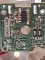
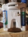
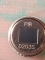
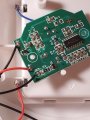
I have no experience with electronics and I need help. I would like to shoot silly string from an inflatable spider. I have a Glade automatic air freshener that I want to use. It has a momentary switch built in to it. I want to use a motion sensor to activate the spray for a second or so so the silly string sprays then spots and the actuator resets. I was able to get it to work with a remote control but I want to automate it. Does anyone know how I can accomplish this? Thanks from a crazy Halloween interactive fan.
Motion sensor momentary switch control
- Thread starter DMP
- Start date

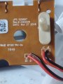

![20201007_215434[1].jpg](/data/attachments/206/206666-fe4352ee701278463d7c217f7995a34e.jpg)


