Most likely failure mode?

Thread Starter

ebeowulf17

Joined Aug 12, 2014
3,307
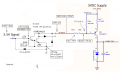
Hey everybody, I've got a large board with one output that's failing, sort of, just a little. There's an output that should always be near ground or near 5V (seems the high end is about 4.75V, which is fine.) We've got hundreds of these working fine, so I'm not trying to diagnose problems in the schematic per se. I'm just wondering what the most likely cause of a one-off failure would be.

When the output should be 0V, it sometimes drifts between 0.5 and 0.7V. Somewhere in that range is just enough voltage to trigger the SSR which the output is connected to and turn on a motor that shouldn't be turned on. It's intermittent and hard to track down.

Any thoughts? Do transistors fail this way, leaking just a little. Would you be looking for a bad joint on one of the resistors? Other thoughts?

MainBoard-Outputs.png
 

Thread Starter

ebeowulf17

Joined Aug 12, 2014
3,307
Sorry that was posted in a rush as I was headed out the door! I'll fill in a few details now that I've caught my bus.

This schematic is a few separate elements from a giant schematic, cut and pasted together. I know it looks weird using a Darlington to drive the base of Q44. It's that way because the Darlington also sinks current for an opto isolator which I didn't copy into this image. As far as I can tell, the opto couldn't be causing this issue, but I figured I should mention it just in case. The high side of the opto is 5V.
 

Thread Starter

ebeowulf17

Joined Aug 12, 2014
3,307
The circuit needs a path for the 3.3 V driven leakage current of the B-C drop of that first transistor to go. It may be 100 nA, but if it has no where to go that's the sort of problems you will have.

You have parasitic capacitances, inductances and leakage paths/

1K is probably too small. 100K should work.
 

#12

Joined Nov 30, 2010
18,224
My analysis, worst case conditions.
For full drive to the SSR the Darlington must saturate to 0.6 volts. It is not spec'd to do that.
Not even close.
Even if it was, you need more drive voltage.
High temperature leakage through the Darlington is more than enough to turn on the SSR when it's supposed to be off.
As a matter of probability, this can be the cause of the occasional mis-fire.
I'm blaming it on the Darlington.

Anyone is invited to correct me.
 

Attachments

Thread Starter

ebeowulf17

Joined Aug 12, 2014
3,307
The circuit needs a path for the 3.3 V driven leakage current of the B-C drop of that first transistor to go. It may be 100 nA, but if it has no where to go that's the sort of problems you will have.

You have parasitic capacitances, inductances and leakage paths/

1K is probably too small. 100K should work.
Interesting... and disturbing. I hate to think that this architecture has such a fundamental flaw.

The specific output I'm asking about here is a relatively new addition - there are 4 outputs per board, and they're only on the latest revision (500-ish boards in the field.) However, I'm pretty sure our boards use essentially the same output circuit for ALL outputs, in every revision of the board... around 20 outputs per board, with thousands of boards in the field. Yikes!

I'll take a closer look at the other outputs in the schematic tomorrow when I get to work.

All of the board outputs drive various kinds of SSRs, all of which have opto input stages. I wouldn't have thought that opto input stages would respond to tiny leakage currents. Are the concerns described above only critical when connecting to more sensitive input stages, or should I be worried about this output design even when feeding opto isolated SSRs?
 

Thread Starter

ebeowulf17

Joined Aug 12, 2014
3,307
My analysis, worst case conditions.
For full drive to the SSR the Darlington must saturate to 0.6 volts. It is not spec'd to do that.
Not even close.
Even if it was, you need more drive voltage.
High temperature leakage through the Darlington is more than enough to turn on the SSR when it's supposed to be off.
As a matter of probability, this can be the cause of the occasional mis-fire.
I'm blaming it on the Darlington.

Anyone is invited to correct me.
Interesting. The more I think about it, the more I think these new outputs are unique... I think the right-hand side with no pull down resistor is probably the same for all of our outputs, but most of the others aren't being driven by a Darlington, and maybe the leakage currents in those outputs are less extreme.

But, wait... even if there's 500uA leakage through the Darlington, shouldn't that feed through R126, and only represent a 165mV drop across R126? If that's correct, I'd still expect Q44 not to be conducting. Don't you need more than 165mV across BE to make anything happen?

I'm confused, but very interested. Thanks to all for comments and analysis so far. Keep it coming!
 

#12

Joined Nov 30, 2010
18,224
Upon further examination, .0005 x 330 = 0.165V
I believe I slipped a digit.
At this point I would examine Q44 leakage and probably give it a path to ground as mentioned in post #5 by KISS

Caution, excuse: I have been awake for 32 hours and I am not surprised that I slipped a digit. That's most of why I invited correction.
 

ebp

Joined Feb 8, 2018
2,332
I don't see anything whatever wrong with the circuit design.

I'd be most suspicious of R126, possibly cracked (SMD?) or possibly a flaky solder joint. The output transistor has pretty high gain - looks like about 500 typ at lowish currents at 25°C from the datasheet curves. With R126 open, leakage in the darlington (or possibly noise) might be enough to cause some grief. The darlington leakage spec is 50 µA max at 50 V at 25°C. 10% (arrived at by unsupportable guess of what typical might be at lower voltage) of that would yield 2.5 mA in the output transistor collector with a gain of 500 if R126 were on vacation.
 

MisterBill2

Joined Jan 23, 2018
27,180
My suggestion also, checking the solder joints of the input stages, and also check and verify the resistance of the 2.7K and the 3K resistors, and check the polarity of that zener diode.Since it is a one-off failure a wrong part is a reasonable suspect. Also verify the connections and the resistance of that 330 ohm resistor, R126.. And the suggestion of a 1k resistor across the zener is a good one. These are the sorts of problems that do pop up on failed production boards.
 
The diode from the 3.0K to the output, if present, could provide a decent leakage path. If it's missing or different, I'd look at that too.

What's the subtle differences between the channel that doesn't work and the ones that do?
 

ebp

Joined Feb 8, 2018
2,332
Everything on the left side of the schematic (left of the tinted area) is internal to the MC1413 IC. The tolerance of the resistors is probably no better than about ±30% since they are fab'd on an IC.
 

Thread Starter

ebeowulf17

Joined Aug 12, 2014
3,307
Well, I wasn't able to determine anything conclusive here, but I'm leaning towards blaming R126. I'm sending it back and I've asked that they replace R126 and Q44. Fingers crossed!

Thanks to everyone for all the help. I've learned a lot about circuit analysis and design from this discussion, even if I don't know for sure what's happening on this particular board. Cheers!

MEB_2018_04-20_Q44.jpg MEB_2018_04-20_R126.jpg
 

kubeek

Joined Sep 20, 2005
5,796
Well, I would do three things. Measure voltages with a known good board, measure a known dead board, an then for a good measure (no pun intended) run it through ltspice. Check what is different and you should be pointed to where the error comes from.
Practically I would suspect leaky Q44 in the first place, or leaky darlington. You should check if R126 actally does its job and is not somewhere open circuit on traces or resistor itself, then remove R128 and check that the transistor stays off.
 
Top