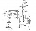
Most Effective Way to Use Generator Output

Thread Starter

madsi

Joined Feb 13, 2015
107
I don't disagree. But suppose the generator and system fail to charge the battery significantly, so that in a year you have to take the battery out for charging 19 times instead of 20 without your generator system. Would you consider that a success?

I'm just saying, it's not clear you won't be disappointed.
I am only disipointed if I don't fully understand why and what works best, I want to fully understand what is the best charging scheme.
 

wayneh

Joined Sep 9, 2010
18,125
Best without using a transformer. ;)

But seriously, you need to define "best". For me, it might be bringing the battery into the house once a week for charging.
 
Last edited:

Gdrumm

Joined Aug 29, 2008
684
Is the bike a 10 speed. If so, could small components be attached to and near the sprockets, that change, depending on the turns ratio of the speed (gear) selected? From there, numerous outputs could be realized, and components matched to produce a more constant output depending on the speed you have selected. Fascinating post...........
 

wayneh

Joined Sep 9, 2010
18,125
Their extremely strong fields would cause the spokes to be momentarily pulled towards the pickup on passing and maybe cause spokes to break or rub the pickup after some time of use.
Do the pickups have an iron core? They may not. The magnets will not be attracted to an air core. The magnets won't add much stress to the spokes, although it is repetitive. The drag stress placed on the spoke by the circuitry is unavoidable since you have to extract the work from the wheel. The power level is so low that I doubt you'll feel it as you ride. The old 6W dynamo, on the other hand, can feel like having the brakes on.
 

Alec_t

Joined Sep 17, 2013
15,125
Still a question remains, what is best?
I thought I'd answered that in post #31 ;). By my analysis the converter method is best at low revs and the direct method is best at high revs. So it boils down to whether your riding is mainly at low speed or high speed.
 

cmartinez

Joined Jan 17, 2007
8,788
Has anyone here suggested this?
It's a boost converter that can rise a voltage at up to 10V, but that by changing a couple of smt resistors can be calibrated to any voltage up to 13V. Also, the price of this board is cheaper than the sum of its parts if you were to buy them separately.
 

Thread Starter

madsi

Joined Feb 13, 2015
107
Do the pickups have an iron core? They may not. The magnets will not be attracted to an air core. The magnets won't add much stress to the spokes, although it is repetitive. The drag stress placed on the spoke by the circuitry is unavoidable since you have to extract the work from the wheel. The power level is so low that I doubt you'll feel it as you ride. The old 6W dynamo, on the other hand, can feel like having the brakes on.

The pickups would function very poorly without it, they have a u-shaped iron piece surounding a coil of very fine wire upon an iron core lamination whose flat end laminated surfaces faces the magnets.
 
Last edited:

Thread Starter

madsi

Joined Feb 13, 2015
107
Has anyone here suggested this?
It's a boost converter that can rise a voltage at up to 10V, but that by changing a couple of smt resistors can be calibrated to any voltage up to 13V. Also, the price of this board is cheaper than the sum of its parts if you were to buy them separately.
This is not my question, my post is not about even to get charging to work, I want to from a quantitative engineering standpoint understand why from calculation and analysis why what works works best.
 
Last edited:

Thread Starter

madsi

Joined Feb 13, 2015
107
I thought I'd answered that in post #31 ;). By my analysis the converter method is best at low revs and the direct method is best at high revs. So it boils down to whether your riding is mainly at low speed or high speed.
Whit what I have been most interested in my posting this topic, all I have been getting is opinion, and an attempt to get some experts in physics on this forum to discuss this topic using math has resulted in the thought police shutting my new topic down.

Please, no "expert opinions", just math and engineering analysis.
 
Last edited:

wayneh

Joined Sep 9, 2010
18,125
The experts have repeatedly told you that no analysis is possible without detailed information regarding the generator. We're still waiting.
 

Alec_t

Joined Sep 17, 2013
15,125
Just what is your analysis, please!
Let's suppose your generator output voltage Vgen is a smoothed 0V to 6V according to revs, the battery voltage is 3.6, and the converter outputs a fixed 4.2V when its input is >= 0.9V.
When the generator output is
a) <0.9V the charge current is zero for both the converter and direct methods,
b) between 0.9V and 3.6V, charge current is (4.2-3.6)/150 = 4mA for the converter method but zero for the direct method,
c) >3.6V, charge current is 4mA for the converter method but (Vgen-3.6)/150 = 16mA for the direct method when Vgen = 6V.

Hence in situation b, converter is best; in situation c, direct is best when Vgen > 4.2V.
 

Thread Starter

madsi

Joined Feb 13, 2015
107
Let's suppose your generator output voltage Vgen is a smoothed 0V to 6V according to revs, the battery voltage is 3.6, and the converter outputs a fixed 4.2V when its input is >= 0.9V.
When the generator output is
a) <0.9V the charge current is zero for both the converter and direct methods,
b) between 0.9V and 3.6V, charge current is (4.2-3.6)/150 = 4mA for the converter method but zero for the direct method,
c) >3.6V, charge current is 4mA for the converter method but (Vgen-3.6)/150 = 16mA for the direct method when Vgen = 6V.

Hence in situation b, converter is best; in situation c, direct is best when Vgen > 4.2V.
Thanks a zillion for your explanation..I am getting closer to understand what is going on.

I don't think you have all values correct.

Here's what I think I know about what is happening:

The converter cannot deliver a constant voltage because the capacitor is drained after the first few pulses.

Scenario 1: Pickup coil feeds sch0ttky bridge rectifier, output connects directly to battery, no filter capacitor.
Result: The battery only charges on generator output pulses during the short period of pulse peak value >bridge drop +battery voltage.
What I guess: Since the coil is unloaded, the voltage rises almost instantly to a charging voltage but almost no power is delivered because of the 150 ohm source resistance and so most of the voltage drop is across this resistance, so very low power is delivered to battery?

Scenario 2: Same as above, but add a 4500uf capacitor after the bridge.
Result: The capacitor charges, depending on pedaling speed, and slowly charges to a peak value >bridge+battery voltage.
What I guess: Since the cap is unloaded, no energy is lost by the capacitor and no current is delivered to the load until the cap charges to the above condition. Any subsequent pulses overflow the threshold of charging and all the available pulse power is delivered to the battery. Should be efficient? No, again, subsequent pulses must drive the low impedance of the battery and filter capacitor so almost all the available energy is lost in the 150-ohm. generator source resistance.

Scenario 3: Same as above, but MC1624 boost regulator is added after cap and bridge.
Result: The capacitor charges to .63V and boost converter starts to work. The capacitor almost instantly delivers all its stored charge to the inductor(minus MOSFET and inductor resistance and ESR resistance of the capacitor). Then the inductor spikes up to a charging voltage which is the schottky diode drop + battery voltage and all power stored in the inductor is delivered to charge the battery.
The power stored in a capacitor in watts is = C*V*V/2.
Guess 1: After the first pulse, the voltage of the capacitor drops below .3V and the circuit waits until the voltage rises again to >.65V to repeat delivering a packet of power.
Guess 2: The voltage of the capacitor drops but not below .3V and the converter makes a series of tiny insignificant charging pulses until Vin <.3V and the converter shuts down.
Guess 3: If I use a LM27313 boost converter instead which has a startup voltage of 2.7V then the capacitor power stored will be again C*V*V/2 but the difference in power delivered to the battery is approx. (1500uf * 2.7 * 2.7) - (1500uf * .9 * .9). With the circuit loses in mind, a higher startup voltage results in much more energy harvested per packet of energy delivered to the battery.
With this device, the voltage drops across the capacitor after the first few pulses to <2.7V and the converter does not try to create weak pulses that just waste available energy. Converter operation only resumes again at 2.7V.
 
Last edited:

Thread Starter

madsi

Joined Feb 13, 2015
107
I'm positive I don't :). We don't have enough info about the generator or the converter.
Yes, all the necessary information is all here for engineering calcuation and analysis, all about the output of the generator, its dependence on speed and is source resistance has been supplied. The circuit for charging the battery is also shown with all circuit component values.
 
Last edited:

Thread Starter

madsi

Joined Feb 13, 2015
107
Maybe this one would work for you:
http://www.linear.com/product/LTC3105
Thanks for your input, but I am not interested in just getting charging to work, I want to understand why what works works best from engineering analysis.

This chip is more complicated, more difficult to work with 10 pins v. 6, extra components are required to fit into the tiny available space and because it is from Linear, it is perhaps too expensive, costing > 12x as much and re-layout of my PCB. Even if this is the best chip for the job, I am looking to understand from engineering analysis why a cheaper, simpler solution like the LM27313 can be made to work as well and why the MCP1624 can cannot.
 
Last edited:

wayneh

Joined Sep 9, 2010
18,125
Scenario 1: Pickup coil feeds sch0ttky bridge rectifier, output connects directly to battery, no filter capacitor.
Result: The battery only charges on generator output pulses during the short period of pulse peak value >bridge drop +battery voltage.
What I guess: Since the coil is unloaded, the voltage rises almost instantly to a charging voltage but almost no power is delivered because of the 150 ohm source resistance and so most of the voltage drop is across this resistance, so very low power is delivered to battery?
It's true that the conduction phase for the rectifier will be brief, or even non-existent if the generator emf cannot exceed the battery voltage. The generator emf has to overcome that of the battery, plus the internal resistance of the battery plus the impedance of the generator coil, but these are all unavoidable facts. Once that limit is met, all the "excess" emf goes into driving current into the battery. Power transfer efficiency is limited by the impedance of the generator. The generator might have maximum power transfer into a 150Ω load, but is seeing only the battery and diodes. These likely present a far lower impedance.

Note that your coil's DC resistance of 150Ω may not tell the whole story. It will also have an AC impedance due to the inductance of the coil. This inductance will have low impact at low frequency (where the DC resistance may dominate) but will become increasingly important at higher frequency (or magnet speed). Tough to predict without data.

Scenario 2: Same as above, but add a 1500uf capacitor after the bridge.
Result: The capacitor charges, depending on pedaling speed, and slowly charges to a peak value >bridge+battery voltage.
What I guess: Since the cap is unloaded, no energy is lost by the capacitor and no current is delivered to the load until the cap charges to the above condition. Any subsequent pulses overflow the threshold of charging and all the available pulse power is delivered to the battery. Should be efficient? No, again, subsequent pulses must drive the low impedance of the battery and filter capacitor so almost all the available energy is lost in the 150-ohm. generator source resistance.
Since the cap is always at the same voltage as the battery, to the circuit it just looks like a tiny bit more battery capacity. This is essentially identical to Scenario 1.
Scenario 3: Same as above, but MC1624 boost regulator is added after cap and bridge.
Result: The capacitor charges to .9V and boost converter starts to work. The capacitor almost instantly delivers all its stored charge to the inductor(minus MOSFET and inductor resistance and ESR resistance of the capacitor). Then the inductor spikes up to a charging voltage which is the schottky diode drop + battery voltage and all power stored in the inductor is delivered to charge the battery.
The power stored in a capacitor in watts is = C*V*V/2.
Guess 1: After the first pulse, the voltage of the capacitor drops below .3V and the circuit waits until the voltage rises again to >.9V to repeat delivering a packet of power.
Guess 2: The voltage of the capacitor drops but not below .3V and the converter makes a series of tiny insignificant charging pulses until Vkn <.3V and the converter shuts down.
Guess 3: If I use a LM27313 boost converter instead which has a startup voltage of 2.7V then the capacitor power stored will be again C*V*V/2 but the difference in power delivered to the battery is approx. (1500uf * 2.7 * 2.7) - (1500uf * .9 * .9). With the circuit loses in mind, a higher startup voltage results in much more energy harvested per packet of energy delivered to the battery.
With this device, the voltage drops across the capacitor after the first few pulses to <2.7V and the converter does not try to create weak pulses that just waste available energy. Converter operation only resumes again at 2.7V.
What happens in this scenario depends on the energy balance, like a bucket with a hose coming in and another leaving. There are 3 states: A) Plenty of generator power is available. The voltage on the capacitor never falls below the minimum required by the boost converter and charging is steady state. B) Low speed, not enough power from the generator. The capacitor is quickly drawn down below the minimum needed by the boost converter. Charging ceases completely. C) Somewhere between A & B, perhaps oscillating on and off.

If you are designing for case C, and it sounds like you are, then you need to know precisely how the converter behaves in this region. What load does it present when it is "off"? How quickly does it transition between on and off, assuming it changes at all? I would say it is probably not meant to operate this way, so this information may be difficult to obtain.

You might need to build in some hysteresis so that you charge a "large" capacitor to a preset high voltage level over several pulses, and when that voltage is reached, you turn on the converter to move the accumulated capacitor charge into the battery. When the voltage falls below the low preset value, turn off the boost and wait for the cycle to repeat.
 
Top