Mosquito Repeller

Thread Starter

iliev986

Joined Oct 29, 2020
20
hi,
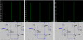
The LTSpice simulator can produce a 'wav' sound file of the circuit output, under simulation test.

E

Added asc file.
Hello again I managed to revive the electrical circuit and it finally worked. Now I was interested in another problem with her. In principle, it should work with batteries from 1.5 volts to 3 volts, but when I put the minimum value of the battery, ie 1.5, something is not right and the circuit doesn't work. I think that something can change the values of the capacity and the electrical circuit is no longer symmetrical in itself. In general, the problem is in the PCB, I guess at least. I do not understand how the voltage in the multivibrator circuit affects the operating frequency. Only the values of capacitance and resistance should affect the operating frequency.
Thanks for all the help from everyone
 

wayneh

Joined Sep 9, 2010
18,104
Hello again I managed to revive the electrical circuit and it finally worked. Now I was interested in another problem with her. In principle, it should work with batteries from 1.5 volts to 3 volts, but when I put the minimum value of the battery, ie 1.5, something is not right and the circuit doesn't work. I think that something can change the values of the capacity and the electrical circuit is no longer symmetrical in itself. In general, the problem is in the PCB, I guess at least. I do not understand how the voltage in the multivibrator circuit affects the operating frequency. Only the values of capacitance and resistance should affect the operating frequency.
Thanks for all the help from everyone
The voltage on the base of Q2 cannot get high enough, and then Q1 cannot get low enough, if the supply voltage is too low. A transistor needs 0.7V on its base relative to the emitter pin to begin conducting.
 

Audioguru again

Joined Oct 21, 2019
6,826
I added a "tran" timebase on the simulation to see the horrible waveform of the buzzer.
The frequency drops only a little when the supply voltage is reduced.
Notice that the simulated 2N2907 transistor survives the 1.05A current overload (rated at 600mA max).
 

Attachments

Thread Starter

iliev986

Joined Oct 29, 2020
20
I added a "tran" timebase on the simulation to see the horrible waveform of the buzzer.
The frequency drops only a little when the supply voltage is reduced.
Notice that the simulated 2N2907 transistor survives the 1.05A current overload (rated at 600mA max).
Does this mean that both transistors need to be replaced?
I was using:
BC807-25 SMD PNP 45V 500mA 0.25W HFE 160-400;
BC847C SMD NPN 50/45V 100mA 0.25W HFE 420-800 ;
 

Thread Starter

iliev986

Joined Oct 29, 2020
20
The voltage on the base of Q2 cannot get high enough, and then Q1 cannot get low enough, if the supply voltage is too low. A transistor needs 0.7V on its base relative to the emitter pin to begin conducting.
Thanks a lot!!!I really notice that the capacitor switches to half the voltage needed to unplug the pnp transistor ,so the duty cycle is interrupted and the schematic is not symetric by itself.
 

Audioguru again

Joined Oct 21, 2019
6,826
It is a horrible circuit. The NPN transistor has nothing to limit its collector current which gives a much too high base current for the PNP transistor.
The speaker is designed to play AC but this circuit gives it DC pulses.

I did not dig up the datasheets for your European BC transistors so you should simply use the 500mA maximum collector current for the PNP and Ohm's Law for the supply voltage and speaker impedance. 3V/8 ohms= 375mA so your BC807 will be fine.
 
Top