Mosfets in series (AND Gate supplying power)

Thread Starter

HiProfile

Joined Mar 15, 2009
33
Questions:
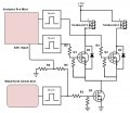
Does this circuit impliment AND-Logic mosfets in series correctly? Do I need the diodes (1n4003?) around the upper mosfets, or other types of protection? Should the upper mosfets have resistors going from gate to source or gate to ground?

I've searched and can't find any similar examples besides versions for signals, and not much that uses the gate to actually power an in-line device. They use additional mosfets in order to pull the signal high or low, and I would like to keep the number of mosfets to a minimum.

Project:
I'm building a circuit designed to open & close multiple solenoid valves in sequence (open & close solenoid #1, open & close #2, etc) with fairly high precision but a fairly low frequency. I'll be using a waveform generator for the main signal, then using an Arduino to handle solenoid selection. The waveform generator's output will also be read back into the Arduino, which will switch channels (turn off one mosfet & turn on another) when it detects the signal's falling edge. My waveform gen does not have enough channels (>2 needed in the future). I'm not using the Arduino for timing because I would like timing to be more precise than I think it can provide.

Specifics:
IRF1404 mosfets (4-20vdc gate tolerance, 75+ amps), 12ohm 1A solenoid valves at 12vdc, waveform generator output is 10vdc & 200Hz with 40% duty cycle, Arduino with 5vdc outputs and inputs.

BTW I have no formal "edumacation" in electronics, so please forgive me if I've used any incorrect terms or designed the circuit poorly. ANY tips or design improvements will be welcomed. Thanks!
 

Attachments

MrChips

Joined Oct 2, 2009
34,626
You are going about this the wrong way.

1) Don't put MOSFETs in series to perform an AND function to supply power.

2) You say your waveform generator does not have enough outputs. You say Arduino is not precise enough.
For controlling solenoids and relays Arduino will work very well. It will give you the number of outputs required and more if needed.
Use the Arduino for timing and outputs.
 

LesJones

Joined Jan 8, 2017
4,511
The Arduino knows the state of the waveform generator output so why not use that to provide the AND function and eliminate the need for Q3 ?

Les.
 

Thread Starter

HiProfile

Joined Mar 15, 2009
33
MrChips, for 2) I should clarify, this circuit is for testing the flow of large batches of solenoid VALVES so I'm looking at making timing as precise as possible. It pulses them several hundred times and I want the only variable to be the valves' flow.

I would be more than willing to let the arduino do all the controls (the program is already written for this), but my friend who does component analysis at a scientific company said his tests showed the arduino to have poor frequency accuracy. My previous microcontroller has proven very repeatable directly controlling timing, but I want more precision if I can have it as well as the extra features an arduino can provide.

For 1) how would I go about this if not letting the arduino do all the work? I want each channel to work up to 5 amps.
 

LesJones

Joined Jan 8, 2017
4,511
I am puzzeled at to why you are using an ADC input for sensing the state of a square wave. An ADC input will be slower than a digital input. If you don't trust the arduino to do the AND function you could just use some gates. I think this would be a better solution than having MOSFETs is series.

Les.
 

MrChips

Joined Oct 2, 2009
34,626
MrChips, for 2) I should clarify, this circuit is for testing the flow of large batches of solenoid VALVES so I'm looking at making timing as precise as possible. It pulses them several hundred times and I want the only variable to be the valves' flow.

I would be more than willing to let the arduino do all the controls (the program is already written for this), but my friend who does component analysis at a scientific company said his tests showed the arduino to have poor frequency accuracy. My previous microcontroller has proven very repeatable directly controlling timing, but I want more precision if I can have it as well as the extra features an arduino can provide.

For 1) how would I go about this if not letting the arduino do all the work? I want each channel to work up to 5 amps.
I am certain the Arduino has more precision than what you need.

What is your definition of precision?
Please respond using numbers and appropriate units.
 

Thread Starter

HiProfile

Joined Mar 15, 2009
33
Honestly I'd be happy if the ardiuno can work great alone!

LesJones, please read the very last line of post #1 for an answer for the ADC input. My limited knowledge lead me to believe the arduino's inputs could only handle 5vdc, be it ADC or digital pins. Regardless of my ignorance, I'm actually hoping there is a very slight lag so the arduino turns the mosfet off slightly after the waveform gen does, and there should be plenty of time before the next waveform gen pulse (3ms). It turns off a channel when the signal falls and immediately turns on another. The solenoid then won't get power until the waveform gen turns on the Q3 mosfet.

MrChips, I would like precision to be 0.01% or better: each square wave should have less than 0.2 microsecond variance from any other, and when a 2ms pulse is requested, it should be no more than 2.0001ms and no less than 1.9999ms. In terms of duty cycle, I want 40% to be no more than 40.002% and 39.998%. I'm also talking about this in terms of the mosfet's output to the solenoid, a very sharp rising & falling edge is required to prevent timing errors. These mosfets work great at 10vdc but can still function well down to 4.5vdc gate voltages. I should also note getting an oscilloscope to test will be very difficult, so I'm trying to hit the proverbial bullseye the first time.

Now I only think it's fair that you guys offer some proof that the arduino can produce a very clean square wave I'm looking for. I fear I'd have to learn about direct port addressing (and rewrite code) if I wanted the most precise arduino outputs. I hate to ask a question outside of this forum's scope, but does anyone have better input on Arduino code to generate multi-channel PWM of 200Hz?
 
Last edited:

AnalogKid

Joined Aug 1, 2013
12,043
If you think about it, there is no extra code needed to fold the AND or enable function of Q3 into the outputs driving Q1 and Q2 because all are governed by the same signal.
Minor point, D1 and D2 already are built into the MOSFETs, so they can be deleted.
You can keep R4 and R5 to attenuate the function generator output but repurpose the A/D input as a standard digital input, the overall latency should decrease by eliminating the A/D overhead.

Starting with the function generator signal, what are the max and min periods and duty cycles?

ak
 

Thread Starter

HiProfile

Joined Mar 15, 2009
33
For 99% of use it will be a fixed 40% duty cycle (2ms pulse), but I'd like to test to 5% (0.25ms) or lower. The period for the generator would be 5ms and I plan to switch 6 on & off 2-400 times each. It's only the ON time that is important, it could be 40%@5ms or 25%@8ms for all I care. 2ms is the common minimum for their application, and the reaction time of each coil varies more then smaller the pulse gets. I figured D1 & D2 were unnecessary, I was just uncertain how mosfets react when their ground (source) is disconnected/floating. I'll also use an arduino digital input. I just now noticed I used "ADC Input" in the pic - I tend to use "ADC Input" for all my Arduino diagrams (sorry I R NOT GUD). That explains the first half of post #7.

I found the following link that goes about improving the basic output code. Regardless of the improvement, his tests show the code I would normally use can take from 4-5.8us switching from HIGH to LOW. I guess I'm at the point now where I have to ask - is the delay identical for LOW to HIGH? If that's the case, they should cross each other out. I'm not interested in exactly WHEN the solenoids are triggered, I'm only concerned about HOW LONG they are triggered for.
(link: https://www.codeproject.com/Articles/732646/Fast-digital-I-O-for-Arduino)
 

LesJones

Joined Jan 8, 2017
4,511
Out of interest I had a look at the ADC conversion times of the ATmega328 (Which is the chip used in the Arduino UNO) The conversion time can be from 13 uS to 260 uS. This is a very significant factor when you are looking at a resolution of 100 nS I was thinking the solenoid vave were normal solenoid valve but as you are looking at such accurate measurments I assume they must use coils with a very low inductance so the current waveform rises rapidly when the voltage is applied. You will also probably have to consider the gate charge and discharge time of the mosfets.

Les.
 

MrChips

Joined Oct 2, 2009
34,626
Honestly I'd be happy if the ardiuno can work great alone!

LesJones, please read the very last line of post #1 for an answer for the ADC input. My limited knowledge lead me to believe the arduino's inputs could only handle 5vdc, be it ADC or digital pins. Regardless of my ignorance, I'm actually hoping there is a very slight lag so the arduino turns the mosfet off slightly after the waveform gen does, and there should be plenty of time before the next waveform gen pulse (3ms). It turns off a channel when the signal falls and immediately turns on another. The solenoid then won't get power until the waveform gen turns on the Q3 mosfet.

MrChips, I would like precision to be 0.01% or better: each square wave should have less than 0.2 microsecond variance from any other, and when a 2ms pulse is requested, it should be no more than 2.0001ms and no less than 1.9999ms. In terms of duty cycle, I want 40% to be no more than 40.002% and 39.998%. I'm also talking about this in terms of the mosfet's output to the solenoid, a very sharp rising & falling edge is required to prevent timing errors. These mosfets work great at 10vdc but can still function well down to 4.5vdc gate voltages. I should also note getting an oscilloscope to test will be very difficult, so I'm trying to hit the proverbial bullseye the first time.

Now I only think it's fair that you guys offer some proof that the arduino can produce a very clean square wave I'm looking for. I fear I'd have to learn about direct port addressing (and rewrite code) if I wanted the most precise arduino outputs. I hate to ask a question outside of this forum's scope, but does anyone have better input on Arduino code to generate multi-channel PWM of 200Hz?
Please find me a solenoid or relay that will have switching times stable to 0.2μs. There are not any of the mechanical kind. Switching times of solenoids are measured in milliseconds not microseconds.

Arduino generating 200Hz signal with a resolution of 0.5μs should be no problem.

I believe you don't have to worry about asking a question outside of this forum's scope. Members on AAC fall into a wide spectrum, many of whom are now retired having spent a lifetime in highly specialized fields of science, engineering and electronics.
 

cmartinez

Joined Jan 17, 2007
8,722
Please find me a solenoid or relay that will have switching times stable to 0.2μs. There are not any of the mechanical kind. Switching times of solenoids are measured in milliseconds not microseconds.
The fastest solenoids that I'm aware of belong to automotive applications, such as fuel injectors for gasoline and diesel engines, and they have (in average) fully-open time lapses of about 200 to 500 μs. Most of them, however, are triggered by a series of high frequency pulses during their opening sequence, and those pulses range between 50 to 150 μs ... And yet, they're still a far cry from the 0.2 μs desired by the OP. So yes, I too am curious about the possible purpose of his question.
 

Thread Starter

HiProfile

Joined Mar 15, 2009
33
The coils switch from to full flow after roughly 1.1ms and I am trying to match that delay to +/- 0.25%. While I know there will be a variance even between pulses of the same coil, I already have to combat fluid temp & pressure variances, variances in pressure between valve ports, baro variances, and even voltage variance. I could easily say 0.5us is "good 'nuff", but I'm curious if I can include a dedicated waveform generator to make it better. What if Intel said 740khz was more than enough for processing power after their 4004 chip?

I only have 2 remaining questions:
1) what form of arduino code is needed for 0.5us of resolution
2) can a dedicated waveform generator be added to improve accuracy?
 

AnalogKid

Joined Aug 1, 2013
12,043
Puttering around the Digi-Key site, this falls out for around $10:
1 pre-packaged crystal oscillator, 2.048 MHz
1 10 bit divider IC (CD4020, etc.)
1 decade Johnson counter, CD4017
1 4093 Quad NAND gate
1 2x8 pin header and a jumper shunt

The result gets you an output pulse width selectable from 0.25 ms to 2.00 ms in 8 steps, all crystal controlled. At this point all the arduino has to do is count the number of on-off cycles and drive an enable line into the divider.

ak
 

cmartinez

Joined Jan 17, 2007
8,722
The coils switch from to full flow after roughly 1.1ms and I am trying to match that delay to +/- 0.25%. While I know there will be a variance even between pulses of the same coil, I already have to combat fluid temp & pressure variances, variances in pressure between valve ports, baro variances, and even voltage variance. I could easily say 0.5us is "good 'nuff", but I'm curious if I can include a dedicated waveform generator to make it better. What if Intel said 740khz was more than enough for processing power after their 4004 chip?

I only have 2 remaining questions:
1) what form of arduino code is needed for 0.5us of resolution
2) can a dedicated waveform generator be added to improve accuracy?
Although I've never used Arduino, I don't see why you couldn't be able to achieve the resolution that you want. Also, I don't think that a dedicated waveform generation would make much difference, since an Arduino's working frequency is more than enough for your specs, and it already works through a crystal oscillator, which is quite accurate in itself too.
 

Thread Starter

HiProfile

Joined Mar 15, 2009
33
Let me back up a step. I'm very passionate about perfecting this, don't ask why. Maybe there's something you guys are equally passionate in, I don't know. Regardless, I am interested in seeing if I can get EVEN BETTER than 0.5us, maybe better than 0.1us.

The problem that arises is the arduino clock frequency doesn't translate into perfect timing
. For instance if I use the micros() code for timing, I can tell it to flip a pin HIGH and that number is effectively divided by 4 - meaning rounded up or down. One gentleman tested this for very crucial timing with PPM signals used with R/C radios, and the 1500us pulse was randomly either 1496, 1500, 1504 - and occasionally 1492 and 1508. That's 16us, not 0.5us. That variance ALONE is over 0.8% at 2ms, meaning all my mechanical bits must have less than a 0.2% margin of error to result in my end figure of +/-0.5%. NOTE: I've bolded and underlined some very important concerns.

AnalogKid, while I appreciate your contribution, I again refer to the last sentence in post #1. All my training is that which I've given myself and I'd be able to rebuild a corvette motor faster than design a circuit with your BOM. Also, didn't I make it clear I already have the waveform generator?

I really don't like to turn away people eager to help me, but I am only seeking 1 of 2 things: arduino coding guaranteed to be accurate to 0.5us or pointers on implementing a known-accurate waveform gen with arduino/mosfet control.
 

AnalogKid

Joined Aug 1, 2013
12,043
So the accuracy of the overall waveform frequency can be whatever the function generator can deliver, but the accuracy of the output pulse widths must be much better - yes?

A crystal controlled high speed clock can deliver extremely accurate pulse widths; just throw money at the crystal oscillator. That's where I started. Once you have a high speed clock and a divider, having it produce the entire waveform just fell out for free in the design.

I wasn't suggesting that the BOM was all you needed. I put it out as an example of the circuit complexity, which is low. I'll see if I can whip up a triggered pulse former schematic.

Do all output FETs turn on and off at the same time?

ak
 

Thread Starter

HiProfile

Joined Mar 15, 2009
33
A high speed clock still doesn't fix the time it takes arduino to address I/O pins or deal with user-friendly code, THAT is where lag is created. It's like having a video card cranking out 400fps but your monitor is capped at 60Hz. Inputs are processes at 4gHz, but there will always and forever be a VISIBLE input lag of at least 16.67ms. Tangential info, but I can absolutely identify even 50Hz vs 60Hz when gaming.

Here are some numbers I found:
Speed in microseconds
Arduino I/O "as is" 5.18us
Arduino I/O without timer check 3.52us
DIO2 with integer argument, non-constant 1.79us
DIO2 with integer argument, constant 1.16us
DIO2 with native argument, non-constant 0.97us
DIO2 with native argument, constant 0.19us

So regardless how precise the arduino's clock is, it still takes at least 0.97us (in my case) with advanced code. That means I call it to open the valve, it takes 0.97us - not really a prob. I ask it to pause 2000us, and it pauses anywhere from 1992us to 2008us - that's a problem. Next I ask it to close the valve, and that takes 0.97us to happen - alone it's not a problem, but it all adds up. So we're anywhere from 7us less or 9us more time. I see 0.5us in comments above, and believe me, I'd love to meet or beat that number somehow!


I guess what I'll do is make a test circuit with JUST the generator controlling one valve and another with an arduino output. I can accurately measure flow to w/in 0.1%, so I'll be able to see if one is better than the other after a handful of tests.
 

cmartinez

Joined Jan 17, 2007
8,722
What language are you using to program the Arduino? is it C?

In my opinion, the only way to guarantee perfect timing is using assembly. That way you will know the exact cycles for each instruction used in your programming.
 

AnalogKid

Joined Aug 1, 2013
12,043
I think we're talking past each other. I'm recommending that all critical timing be done outside the arduino in hardware, with the arduino as a test cycle manager (you mentioned a variable number of cycles in a test).

ak
 
Top