MOSFET will not turn off regardless of polarity

Thread Starter

ballsystemlord

Joined Nov 19, 2018
256
Hi!
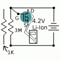
I am using an IRFZ44N N-E-MOSFET. Pictured below (hand drawing, correct me as needed). is my MOSFET and how I hooked it up. I expected that the MOSFET would be on in the schematic and off if I hooked it to the opposite side of the resistor. This is not the case.
I tried lowering the resistance with the pictured 1K resistor (1K + 3M), but that did not work either.
I tried reversing the polarity of my tester without effect.
I tried disconnecting one side of the battery and then connecting only the other side (so the + or - terminal was shorted to the MOSFET's gate).
I finally used my TC-1 component tester to verify that the MOSFET was working and hooked up correctly and it was.

Thanks!


Attachments

wayneh

Joined Sep 9, 2010
18,181
Hi!
I am using an IRFZ44N N-E-MOSFET. Pictured below (hand drawing, correct me as needed). is my MOSFET and how I hooked it up. I expected that the MOSFET would be on in the schematic and off if I hooked it to the opposite side of the resistor. This is not the case.
I tried lowering the resistance with the pictured 1K resistor (1K + 3M), but that did not work either.
I tried reversing the polarity of my tester without effect.
I tried disconnecting one side of the battery and then connecting only the other side (so the + or - terminal was shorted to the MOSFET's gate).
I finally used my TC-1 component tester to verify that the MOSFET was working and hooked up correctly and it was.

Thanks!

The voltage that matters is the ∆V between the gate and the source pins. In your circuit both the drain and source pins are floating. They may have a voltage difference induced by attaching the meter, but the ∆V between gate and source is undefined. This may have damaged the MOSFET.

It's normal to attach the source to ground and the drain pin to the negative side of your load, such as a lightbulb. The positive side of your load connects to the battery positive pole. Then, when the gate voltage is high enough above ground, the MOSFET will conduct and the load will have a path to ground and light up. Note that the resistance between drain and source will be very low when the MOSFET is on - it's like a switch. So if you use an LED you'll need to limit the current or you'll toast it.
 

AnalogKid

Joined Aug 1, 2013
12,287
Whether or not a MOSFET is "on" depends on the voltage between the gate and source, called Vgs. In your schematic, the source is not connected to anything (the meter doesn't count), so Vgs doesn't exist.

The battery is upside down in your schematic. Reverse it so the wide bar (the anode, or + terminal) is to the top and the narrow bar (the cathode or - terminal) is to the bottom. The - terminal will be circuit ground (GND) net. Connect the source to GND. Then as you move the gate from GND to 4.2 V, you should see a change.

ak
 

Reloadron

Joined Jan 15, 2015
7,975
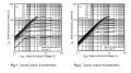
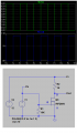
This is your power MOSFET including the characteristic charts above. Yes, as drawn you can't just have the Source and Drain floating and apply a voltage to the Gate as the Gate voltage will not be referenced. You want to have your setup like the below.

IRFZ44N.png
R1 is to make sure that the MOSFET turns off when it should and R2 is merely serving as a load. Again, the gate voltage needs a reference to the source.

I see Scott just added more information.

Ron
 

Thread Starter

ballsystemlord

Joined Nov 19, 2018
256
Thanks guys, with a working schematic, I was able to isolate my problem. I am using a bread board. Up until now I have just used alligator clips, wrapping the wires together, and for more permanent projects; solder. As it turns out, inserting wires into the breadboard does not work. They fail to make good contact. So, I have to use wires with metal tips.
Thanks!
 

dl324

Joined Mar 30, 2015
18,490
As it turns out, inserting wires into the breadboard does not work. They fail to make good contact. So, I have to use wires with metal tips.
What type of wire were you using? Solderless breadboards work best with solid #22, but you can usually get away with #24.
 
Top