MOSFET switch always on

Thread Starter

carto

Joined Feb 3, 2014
45
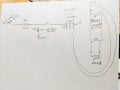
Hi, my MOSFET switch is always on. I need it to switch 12 V power on and off with the signal from an Atmega328P-PU pin. I have attached a diagram of the circuit. Can someone see what's wrong? Thank you!
 

Attachments

Sensacell

Joined Jun 19, 2012
3,432
I do not see any connection between the ATmega ground and the circuit?
The MOSFET is also backwards, the body diode is conducting - so it's always ON.


You need to connect the 12 V GND and the MCU GND together.
Connect the MOSFET Source terminal to GND, the drain connects to the converter "-" terminal.
 

crutschow

Joined Mar 14, 2008
34,281
Yes, the MOSFET is N-channel, so the drain must be more positive than the source.
You have it connected opposite.
The only way it will work is to use it as a low-side switch with the source grounded, but that requires that the DC-DC converter has the input common isolated from the output.
Is that the case?

If not, then you need to use a P-MOSFET with and an NPN driver.
 

Thread Starter

carto

Joined Feb 3, 2014
45
Edit: I deleted the schematic that was attached; it was incorrect around the MOSFET.

Thank you for the replies! I could go through and figure out how to answer your questions, but first, since I'm such a novice, maybe posting more of the circuit would help (attached)?
 
Last edited:

crutschow

Joined Mar 14, 2008
34,281
To control the power from a 4V Atmega signal you could do this:
Q1 can be just about any small NPN transistor, and M1 can be any P-MOSFET that has at least double the current-rating of what the DC-DC converter requires.

1612323279585.png
 

Sensacell

Joined Jun 19, 2012
3,432
If your DC - DC module is NOT an isolated converter, you cannot use an NFET to switch it, you need to use the circuit in post #5.
 

dendad

Joined Feb 20, 2016
4,451
I the reg actually a LM256?
If it is an LM2596 or similar "Simple Switcher", you may just be able to toggle the chip's enable line. No FET needed.
 

Thread Starter

carto

Joined Feb 3, 2014
45
It is an LM2596 on an HW-411 board. I am building a very low-power system that turns off the 12 V power completely between photos. As for the circuit diagram with the NPN transistor: I already have NFETs; could something similar to this circuit be used with the NFET?
 

dendad

Joined Feb 20, 2016
4,451
If you lift pin 5 of the LM2596 off the board, then drive a small FET or transistor to pull the pin 5 low, with a pullup resistor from pin 5 to +12V.
Then the Arduino can drive HIGH to hold the regulator on, and LOW to turn it off.
You could add a pushbutton to it to manually turn it on, connected between pin 5 and 0V. Then the Arduino holds the power on until it is finished.
I'd try that and see.
 

crutschow

Joined Mar 14, 2008
34,281
The LM2596 has a Low Power Standby Mode, typ 80μA, so dendad's suggestion should work without significantly affecting the battery's charge when off.
 

Thread Starter

carto

Joined Feb 3, 2014
45
I like the idea of trying to deal with the LM2596 directly, but I am using the HW-411 board that also contains the chip's required components, and I have mounted the HW-11 atop a custom PCB that in turn has the rest of the components I am using. I think it would be beyond my capability to strip down the HW-11 and put that onto the PCB. So I don't know that I could get at that lifted pin of the LM2596.
 

Thread Starter

carto

Joined Feb 3, 2014
45
I can certainly redesign the circuit. A bit of background: I need to minimize power consumption. I am taking one photo every 2 hours for 5 months. The camera power (provided from a 12V battery converted to 8V) is turned off between shots, and the power consumption through the Atmega chip (provided by 3 AAA batteries) is also minimized (it sleeps between photos and wakes up with a clock-chip alarm). In a previous version I used a latching relay to control the 12V power but on a PCB the clock would occasionally reset--I thought perhaps related to the action of the relay. I thought that the MOSFET would act like the relay but with less disruption to the circuit. But apparently switching the 12V battery-converter-camera is different from switching, say, an LED (which I think works with an N-channel MOSFET)? Would the P-channel design leak more current? Thank you!
 

crutschow

Joined Mar 14, 2008
34,281
But apparently switching the 12V battery-converter-camera is different from switching, say, an LED (which I think works with an N-channel MOSFET)?
The only difference is that the LED can use a low-side switch (N-MOSFET source connected to ground with the LED connected to the drain and going to V+).
As noted, the DC-DC converter must be connected to ground and thus needs a high-side P-MOSFET switch (source connected to V+).

You can't use an N-MOSFET as a high-side switch unless you have a gate drive that's 5 to 10V above the source (depending upon the MOSFET Vgs threshold voltage).
Would the P-channel design leak more current?
No, the leakage of either type of MOSFET is negligible for your purposes.
 
Last edited:

Thread Starter

carto

Joined Feb 3, 2014
45
But with the P-type, doesn't the Atmega pin need to be high to hold the 12V power off--and doesn't this consume AAA power? I think I need to put the Atmega to sleep between photos. I apologize if I have this wrong--I'm learning as I go.
 

Thread Starter

carto

Joined Feb 3, 2014
45
I think I found my answer:
"When the PIC output is LOW, the transistor is OFF and the gate of the P MOSFET is HIGH (12V). This means the P MOSFET is OFF."
 

Thread Starter

carto

Joined Feb 3, 2014
45
Spidey, yes the depiction is accurate. Yes, the grounds are all tied together. The clock (DS3231) is also ground with them.
 
Top