Thanks for the help guys. The IR2117 is now ordered and hopefully it will be here in a few days. Hopefully I don't have to buy more mosfets for a while!
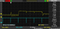
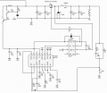
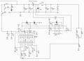
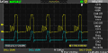
Now I have finally got the ir2117 driver. So I have just started testing but I can not get it to work properly. When the voltage gets above a certain value (~12v) the gate signal acts weird. I have attached a screen shot of this from my oscilloscope, here the blue wave is the signal from pwm controller and the yellow is from ir2117 to mosfet gate. You can also see my schematics. I have tried changing both the capacitor and the resistor values but the same happens every time, but at a little different voltage. I have also tried with a zener diode in parallel with the bootstrap capacitor, and a diode in parallel with the resistor between mosfet gate and ir2117, but with no results.
It looks like your PWM controller output is near 100% duty-cycle, thus you would expect the output to go high. The small blips are because the input negative pulses are too short to completely turn off the gate. Try it with a lower duty-cycle.
Also why is the value of C12 so small? It's not a compensation capacitor. It has to provide the charge to the large gate capacitance when the transistor turns on. I would suggest at least 1μF.
What type of diode is D6?
What is the input supply voltage and the logic (VCC) supply voltage?
Edit: A value of 0.1μF should be adequate for C12.
The problem is that due to the gate driver is not doing its job the pwm signal will alway be near 100% duty-cycle.
The value for c12 in my schematics is not correct as you point out. Here I tried different values around 0.1uF (and 1 uF) but it does not change anything.
D6 is a ultrafast high voltage diode (STTH100W06C), I know it is a bit over-sized but it should handle the job fine.
Both Vcc and the pwm signal input is 20v.
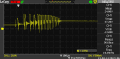
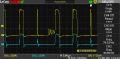
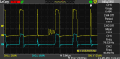
I have now tested with a signal generator to test for a lower duty cycle. The measured gate signal to the mosfet is attached. Here the duty-cycle is around 50% and the frequency is 40k Hz. As you can see the the signal turns on, then it looks like a very messy pwm signal for some time (at a very strange frequency), until it stops behaving weird and is only high for some time, until it finally turns off and starts over again. I really hope you can help me with this, all suggestions are appreciated!
Do you have a decoupling capacitor (typically 0.1μF) directly at the Vcc pin of each IC directly to ground pin. Those are necessary for proper circuit operation.
How is the ground constructed? You need a low impedance ground (typically a ground plane) to minimize ringing and oscillations in such a circuit.
So finally I got my circuit to work! At least until i tested for higher voltage... And now none of my gate drivers (ir2117) is working anymore...
So I need some new ideas from you guys. My last posted schematics is still valid, but I have added a capacitor from Vcc to COM at ir2117 and changed the value for bootstrap capacitor to 470nF.
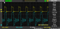
So while things worked as intended i took some screenshots from my oscilloscope, and I am wondering if the waveform is correct. The yellow one is my pwm signal from the gate driver while the blue one is the source leg of the mosfet. Both is refereed to ground.
What do you think about this waveform?
So guys,
I have come a little closer to have a working buck regulator. Now it works good at low voltages (up to 30) but at higher voltages the output voltage goes to zero. It looks like the mosfet stops switching because the ic's turns off. I am concerned that my regulator is operating in discontinuous mode but I dont know if that is what causes my problems. How to get out of discontinuous mode?
Frequency is now at 40kHz.
What is the Vcc you are using for the IR2117? Ealier you said 20V, you are slightly high with that. There is no real advantage with going over 10-12V on the mosfet gate. If when increasing the circuit input voltage you have exceeded the max gate voltage of your mosfet, that may be the problem.
Thanks for reply.
I got rid of the problem with no pwm signal to the mosfet by restricting the ground potential around the IC's. So now it works nicely up to around 50v (independent of current consumption). Then it starts bugging. When scoping the gate-source voltage I find that every second pwm signal is fine and the rest is too small and too low to turn the mosfet fully on. This creates much noise at output and generates much heat in the mosfet. I have now changed the gate voltage to 15v.
What do you think is the reason for this? If change the frequency the voltage level where it starts bugging is moved a little (a few volts up or down).
I took some screen-shots to show you better what is happening. In all the pictures the yellow signal is pwm signal from gate driver and the blue is gate-source voltage at the mosfet.
The first picture shows a level when the regulator works. The oscillations might be due to discontinuous mode but please comment this.
The next shows the situation when it starts bugging. Here I need some tips on how to get rid of the small duty cycles.
To avoid discontinious mode, you need some minimum load.
Also, the bootstrap capacitor gets charged during the conduction period of the freewheeling diode. Can you also check the PWM output and the gate driver output? If the PWM output is wide and the gate driver output is the spike, that means that there is not enough charge left on the bootstrap cap.
In fact, you define the minimum load, and then calculate the inductor needed. Can you please give your specifications? Vin (Min & Max), Iout (Min & Max) and Vout(~14V I guess from the divider values).
For 2A Imin, @43kHz., Vin=50V, L should be above 60uH. At Vin=300V, L > 85uH, approximately.
The pk-pk inductor ripple current is 4A, and the output cap should be rated for this alongwith a low esr which would keep the output ripple low. For this ripple current rating, the capacitor value would normally be higher, and decides the output cap value rather than the time constant multiples.
For this ripple current rating, the capacitor value would normally be higher, and decides the output cap value rather than the time constant multiples.
I am a little concerned that the duty-cycle will be too small for the mosfet at 300v, making the mosfet not able to turn on. Any ideas how to handle that?
And after a short search it appears the higher inductor value the lower current it is able to handle. So how to get a good inductor for high currents?
Can you wind one? Core can be T184-26, T200-26 or T200A-26, Iron powder core, Yellow White, Material #26. I have selected a slightly larger core to accomodate the wires. But check the wire accomodation. For 100uH, using the above cores, 25, 33 & 25 turns respectively, would be required. The cores are available at http://www.amidoncorp.com/26-material-iron-powder-toroids/?sort=featured&page=2
Thanks for the tips RamaD,
so you think 1us should be enough for the mosfet to turn on properly?
I am a little worried because at these small duty cycles (see picture, here the mosfet voltage is the blue curve and the yellow is the pwm signla from gate driver) the mosfet is not operating properly and gets hot. It looks like the mosfet does not turn fully on, and my inductor starts making a strange sound.
point one: 10uh is not alot of inductance. the longer the mosfet is on, the more potential difference it developes between source and drain, which in turn produces heat (Heat in Watts = V * I), at 300v, you need nano seconds for the gate to be on each cycle!!!! or increase the inductor!!! for 300v, i STRONGLY suggest at least 100uh!!! 500uh would be good for the mosfet to be on for like 3 micro seconds.
Point Two. having the source connected on the positive side of the circuit means the gate has to be at a much higher voltage then the circuit for the mosfet to be fully switched on, otherwsie it acts as a resistor. (unless its a P channel mosfet)
Point three. having the N channel mosfet on the negative side of the circuit will make sure the potential difference between source and gate will remain constant and will not vary. this will also mean the on resistance will be very minimal depending on what voltage you provide to the gate and what the turn on voltage is for that particular mosfet. got a datasheet for the mosfet?
Point four. Do you research in electromagnetism if u are going to do this sort of stuff.

 Facebook
 Google
 GitHub
 Linkedin