mosfet overheating

Thread Starter

dcd528

Joined Jul 28, 2011
46
I have a circuit that has worked in the past. I just reworked it and now the mosfet is overheating. Prior to the rework I had intermittent overheating but now it blows the mosfet all the time.
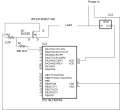
I've attached a schematic. Basically I have a microchip that senses an input and if the mosfet should be on it causes a pin to go high. The high signal is sent to the gate of the mosfet, buffered with a 330 ohm resistor. There is a 2.2K pulldown resistor gate to ground. The input power is 1.3A at 9Volts.
The load is a heating element, nichrome wire. I have the V+ from the power supply going directly to the nichrome and then the other end of the nichrome goes to drain of the mosfet.
The mosfet is IRFL014 from vishay, this is suppose to have max ratings of 60V and 2.7 A.
The voltage regulator is 5V 1.5A.
Resistors are 1/8 watt
Seems the mosfet should handle the load but since I am just a tinkerer without EE training I'm not sure where I went wrong. Any help would be greatly appreciated.
The original schematic had S / D reversed I just moved the labels to "fix it"
 

Attachments

Last edited:

wayneh

Joined Sep 9, 2010
17,498
As drawn, the MOSFET is oriented wrong. The drain should face the load, and the source should face ground. Otherwise the body diode is conducting and cannot be switched off.

Also, you should raise R2 or decrease R1, or both. They divide down your control voltage and the MOSFET will not turn fully on. You could use a logic level MOSFET instead, and that would help. In fact I'd say that is mandatory, even if you can get a full 5V onto the gate. That's just not enough for a regular MOSFET.
 

Thread Starter

dcd528

Joined Jul 28, 2011
46
As drawn, the MOSFET is oriented wrong. The drain should face the load, and the source should face ground. Otherwise the body diode is conducting and cannot be switched off.

Also, you should raise R2 or decrease R1, or both. They divide down your control voltage and the MOSFET will not turn fully on. You could use a logic level MOSFET instead, and that would help. In fact I'd say that is mandatory, even if you can get a full 5V onto the gate. That's just not enough for a regular MOSFET.
Thanks for looking. I actually screwed up the schematic and reversed S and D. I do have the
As drawn, the MOSFET is oriented wrong. The drain should face the load, and the source should face ground. Otherwise the body diode is conducting and cannot be switched off.

Also, you should raise R2 or decrease R1, or both. They divide down your control voltage and the MOSFET will not turn fully on. You could use a logic level MOSFET instead, and that would help. In fact I'd say that is mandatory, even if you can get a full 5V onto the gate. That's just not enough for a regular MOSFET.
I fixed the schematic and uploaded it. I had S and D reversed in the original.
If I just remove R1 might that work?
I ordered this part from digi key SSM3K337RLFCT-ND
If that fixes my problem I'll be one happy camper.
thanks much
 
Last edited:

ronv

Joined Nov 12, 2008
3,770
It should work, but take the advice above and make the gate resistor around 22 ohms and the gate to source about 27K. Anything around that is ok.
 

Thread Starter

dcd528

Joined Jul 28, 2011
46
It should work, but take the advice above and make the gate resistor around 22 ohms and the gate to source about 27K. Anything around that is ok.
ok I have 39 ohm and 39K resistors on hand, I'll try those when I get the new mosfet. I measured the resistance source to drain and when the on signal was present the measurement was 0.2 ohm. Is there something else going on that prevents the device from being "on" even though the resistance is low?
 

SgtWookie

Joined Jul 17, 2007
22,230
What does your board layout look like? You should be using nice wide traces and a good-sized pad for the tab to provide heat-sinking; ideally with vias linking the pad to another on the other side of the board. The MOSFET is rated for 2.7A only when the body is at room temperature; at 100c it drops to 1.3A; barely adequate. With such a marginal MOSFET, you will need to pay extra attention to cooling.
 
Last edited:

Thread Starter

dcd528

Joined Jul 28, 2011
46
What does your board layout look like? You should be using nice wide traces and a good-sized pad for the tab to provide heat-sinking; ideally with vias linking the pad to another on the other side of the board. The MOSFET is rated for 2.7A only when the body is at room temperature; at 100c it drops to 1.3A; barely adequate. With such a marginal MOSFET, you will need to pay extra attention to cooling.
thanks I appreciate the input, I'll modify accordingly
 

SgtWookie

Joined Jul 17, 2007
22,230
You don't show what your power in voltage is, but I suspect it's around 5v.
You've selected a 100V MOSFET, and I'm not sure why?
Usually, you'll want to select a MOSFET that has a max Vdss rating not much more than will normally be across it. That's because max Vdss, Rds(on), Id and Qg are all interrelated. When your Vdss goes up, your Rds(on) will go up and Id will go down for a given Qg.
When your Vdss goes down, Rds(on) goes down and Id goes up for a given Qg.
If you're dropping voltage across a part, it's going to dissipate power as heat. You need to be able to get rid of that heat, and it helps a great deal to minimize the heat generated in the beginning.
 

Thread Starter

dcd528

Joined Jul 28, 2011
46
ok I ordered that part (NTD4906N). I really don't know all the technical details that you gurus do which is why I'm asking for help. Thanks for helping. I've been tinkering for years but get lost in the datasheets. I just figured that the higher the V rating the more the mosfet could handle. Now I know better. I'll let you know how it works out. The power in is 1.3A at 9V (wall wart) or LiPo battery rated at 7.4 V and 1000 mAh
 

ronv

Joined Nov 12, 2008
3,770
Yes, the other thing is current.
That one will work to switch it.
You aren't trying to charge the battery with this arrangement are you?
 

Thread Starter

dcd528

Joined Jul 28, 2011
46
Yes, the other thing is current.
That one will work to switch it.
You aren't trying to charge the battery with this arrangement are you?
no, I do have a separate charging circuit with the appropriate microchip charging chips. I have used it a couple of times without problem.
 

Thread Starter

dcd528

Joined Jul 28, 2011
46
To all who responded thank you. I ordered and installed the NTD4906N that RonV suggested and it works great. MOSFET is cool to the touch. So as a thanks if anyone who is currently on this thread needs any machining done I can do small parts (4" x 4" or so) out of aluminum, brass or mild steel. I have a bench lathe and bench mill and can hold +/- .003" (probably can hold tighter than that, depends on the part). Send an email to dcd528 at hotmail dot com and post to this thread saying you emailed me and I'll make you a free part (as long as it is not super complicated).
Again thanks so much for the help, I would still be banging my head against the wall.
 

Thread Starter

dcd528

Joined Jul 28, 2011
46
The drill/mill is a little one, an earlier version of this http://www.grizzly.com/products/4-x-18-3-4-HP-Mill-Drill/G0781
The initial cost (about $750) isn't bad but then all the tooling gets expensive. I bought a rotary table which was a couple hundred dollars, almost a third of what the mill cost.
The lathe is this one http://www.grizzly.com/products/10-x-22-Bench-Top-Metal-Lathe/G0602. I also have a fireball v90 cnc router but that only cuts wood. I haven't done any fancy 3D wood working but I have cut some intricate parts with recesses, steps and spirals.
Happy to make you a part if you need one, least I could do - you saved my project, and saved me hours of trial and error.
 
Top