mosfet overheating in ozone generator

Thread Starter

danydevito1984

Joined May 11, 2022
6
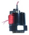
Hello, I have a circuit to generate ozone through a flyback shunt transformer using two IRFP250 mosfets, the problem is that they overheat a lot and burn.
The mosfets do have cooling. The circuit is powered by 12VDC and uses a flyback transformer. Please your help indicating what the problem of said overheating would be. Attached ozone generator circuit.
 

Attachments

sagor

Joined Mar 10, 2019
902
Maybe add a back EMF diode across each transformer input.
Also, a grounding resistor (10k?) from each gate to ground may help drop gate voltage quicker, to prevent MOSFET from operating "in between" range of full on/off.
 

Ian0

Joined Aug 7, 2020
9,618
Maybe add a back EMF diode across each
That would prevent it from being a flyback transformer, by limiting the primary flyback voltage to 0.6V.
The voltage should be clamped as high as possible using a diode in anti-series with a zener,
Also, a grounding resistor (10k?) from each gate to ground may help drop gate voltage quicker, to prevent MOSFET from operating "in between" range of full on/off.
The 3525 has a push-pull output, so doesn’t need a pulldown resistor.
 

Thread Starter

danydevito1984

Joined May 11, 2022
6
Maybe add a back EMF diode across each transformer input.
Also, a grounding resistor (10k?) from each gate to ground may help drop gate voltage quicker, to prevent MOSFET from operating "in between" range of full on/off.
An important fact is that the voltage on IC 3525 measured at output A 11-13 and output B 14 -13 is equal to 6.4V.
The capacitor and resistor at each gate of the mosfet is 0.1uF and 1K.
 

Thread Starter

danydevito1984

Joined May 11, 2022
6
That would prevent it from being a flyback transformer, by limiting the primary flyback voltage to 0.6V.
The voltage should be clamped as high as possible using a diode in anti-series with a zener,

The 3525 has a push-pull output, so doesn’t need a pulldown resistor.
An important fact is that the voltage on IC 3525 measured at output A 11-13 and output B 14 -13 is equal to 6.4V.
The capacitor and resistor at each gate of the mosfet is 0.1uF and 1K.
 

shortbus

Joined Sep 30, 2009
10,045
The capacitor and resistor at each gate of the mosfet
Just a hobbyist thought.. Why are you adding a capacitor to the gate? The gate its self is a cap and adding another could be slowing down the gate discharge and allowing a "shoot through", which will cause the mosfets to both be on and fighting against each other and causing heat.
 

Ian0

Joined Aug 7, 2020
9,618
Just a hobbyist thought.. Why are you adding a capacitor to the gate? The gate its self is a cap and adding another could be slowing down the gate discharge and allowing a "shoot through", which will cause the mosfets to both be on and fighting against each other and causing heat.
A capacitor as shown will speed up the gate rather than slow it down. It might make it more prone to oscillation.
10Ω in series with or without a diode in parallel to speed up the switchoff would be more conventional, and is known to reduce oscillation.
 

Thread Starter

danydevito1984

Joined May 11, 2022
6
Solo un aficionado pensó ... ¿Por qué está agregando un condensador a la puerta? La puerta en sí misma es una tapa y agregar otra podría ralentizar la descarga de la puerta y permitir un "disparo", lo que hará que los mosfets estén encendidos y peleen entre sí y causen calor.
[/CITA]

What you're suggesting is that I remove the gate capacitors and leave just the resistors...?
 
Top