Mosfet keeps blowing up power switch, circuit design error?

Thread Starter

BkraM

Joined Jan 19, 2014
24
Hi All,

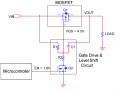
I'm using circuit below
upload_2018-10-3_12-25-21.png
Q2=2n7000A; Q1=IRF9540N
C1=not installed; R1=R2=10k; Vin = 15V; gate Q2=0 or 5V

The circuit is used to switch on power with an Arduino. This (in principle) works fine.
After using te circuit for 10, times Q2 failed. Which can happen I suppose.
I've replaced it, and after some usage it is burned again....

Chances are there is something wrong here causing Q2 to fail, not sure what that is. Any help is appreciated.

The load used so far is only a led with a resistor, it will be used to power an H-bridge connected to a coil (+/- 1A).

Thanks,

I see there is a "p" missing in the title, but can't correct is apparently..
 

Attachments

Last edited:

danadak

Joined Mar 10, 2018
4,057
Something really crazy here, essentially because of R2 = 10K
there is no load on 2N7000.

Wiring error ?

Try subing a NPN small signal for Q2, use a base R from UP to
base Q2 of 4.7K for starters.

Check R1 and R2 are in fact 10K ohms with DVM.

Maybe you have defective 2N7000's. Is there a long lead from
UP to 2N7000 gate input ? Thinking L effects blowing gate.

Does the bad 2N7000 overheat, if so it is a wiring error. If not is
gate still High Z with respect to source or drain led ? With gate
shorted to source is Drain to Source resistence real high or
shorted ?

Regards, Dana.
 
Last edited:

MrSoftware

Joined Oct 29, 2013
2,196
Check your physical R1 and R2 and make sure they are really 10k. Also check the gate on Q2 and make sure it's really 5V. Lastly can you get an ammeter in there to see what the actual current is across Q2? This could help indicate a wiring error as @danadak mentioned.
 

ScottWang

Joined Aug 23, 2012
7,398
Q2 = 2N3904 (NPN) or small signal npn transistors and in series with a 2.2K ~3.3K resistor, or depends on the Vin from uC to change the values of resistor.
R1 = 10K, R2 = 4.7K. (Dana already suggested that value)
 

Picbuster

Joined Dec 2, 2013
1,047
circuit should work!
But a small resistor(50Ohm) in series with the gate of q2 might solve the switch on current generated by the MPU.
Please measure the drain source voltage when in saturation.
Increase R1 to 47K or so when your system is slow switching.
( The FET is voltage driven)

I do use r1=100K r2=2k2
Mosfet Sqj407 or irf9388pbf
Q2 = DMN100-7-F

Use this to PWM 12V 3 Amp @ 4Khz to feed a heater.
It does look like a problem with wires as stated before.

Picbuster
 

Thread Starter

BkraM

Joined Jan 19, 2014
24
Thanks all,

Good to know there is nothing wrong with the circuit. Will check the wiring, and add the resistor to see if this fixes the problem.
 

danadak

Joined Mar 10, 2018
4,057
If you have a DSO you can set it for one shot mode, eg. a single sweep, and set
trigger for Vgsmax of the MOSFET and look for a out of speck spike, typically
from inductance in circuit, layout.....

Do same for power supply rail, trigger off Vrail max + 1 volt or Vground - 1V,
this will help with checking your bypassing effectiveness.

Whne using caps for bypassing typically use a ceramic, say .1 uF, and a bulk
cap. Not not all caps, for same C vaklue, have same performance.


Regards, Dana.
 

Thread Starter

BkraM

Joined Jan 19, 2014
24
Added a 680 ohm resistor to the gate. And did sime cleaning up of the solder traces to be sure there is no (small) connection between tracks. No weird stuff going on looking at it with a scope.

Seems to be work fine now... lets see if it will last this time.


Thanks
 
Top