Facebook
 Google
 GitHub
 Linkedin

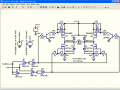
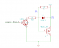
I'm designing an H-Bridge to handle 24v and up to 2A loads. The MOSFET gate operation is controlled by a TTL logic signal that is level shifted by a BJT so that Vgs = Vds when the device is on. My understanding is that this forces the MOSFET to either be off or in saturation mode.
What concerns me is what is Vgs actually going to be under various motor loads; If I use a part with a 20v gate oxide breakdown voltage is the MOSFET going to breakdown if the motor stalls giving a Vgs = ~24v
Or should I stick a voltage divider in there and supply the gate with a voltage around where the RDS(on) curve flattens out.
Attachments
-
15 KB Views: 113