mosfet driven cdi design help

Thread Starter

Evanguy

Joined Dec 21, 2014
85
i would like to say hi first off, im new here and i have a question or even more so i could just use your opion or advice with my attempt at designing a circuit

so im pretty new to electrical circuits and im trying to learn, i learn best by doing opposed to reading text books, and i find looking at circuits that i know what the outcome is, is the most help full, but i have a hard time understanding why things are used where they are in circuits. im starting a huge project for a beginner and the plan is to one day make an ecu, i bought a new 5hp briggs and stratton for this project and i plan to make it run via fuel injection and my own pickup and cdi unit, i want to make all the efi and spark components my self,

i have have a few drawings of what im planning to build, some were copied with slights mods to them by me and the others were conceived ideas i just changed around the parts, as of now i have a injector controller using a lm1949 (very close to the circuit in the data sheet with few mods) i have a us1881 hall sensor circuit i plan on using for the pickup and i have an arduino due (84mhz) for the ecu its self. im not even getting into the programing of this yet, i do know about bit about that part though. for right now i want to build the major circuits then connection them to the motor one at a time and making them work together. the motor starts now its brand new, i want to remove all spark/pickup components and use my own to get it running with no advanced spark first.

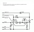
so here is the circuit i made with the ideas and design coming from others. i would like some input on it as i dont know very much and im trying to learn. basicily i wonder things like, why are the .001uf caps there and do they go before or after the resistor or diode. does this circuit look usable or am i missing something. oe what changes would you make and why.

im obsessed with building motors and making things, im a machinist and i make everything one can imagine. but this is the first getting into electronics of things even though i use them everyday.

any insight or comments are welcome. and before one asks im not sure where im geting 400v dc from, thats a later project, when i understand a bit more. i have ordered all the parts in all my drawings as well as many more related components. i have no problem ordering more, this is my new hobby i can sink some money into it lol.

thanks
 

crutschow

Joined Mar 14, 2008
34,280
I don't understand the purpose of C2. You want a fast signal at the gate of the MOSFET so it rapidly turns on, and C2 will just slow down the gate signal, which seems undesirable.

You are applying less than 5V to the MOFSET gate but, if you look at the ON resistance test value in the spec sheet for that device, you will see that it's done at a Vgs of 10V, thus you should apply at least that much voltage. Alternately you can buy a logic-level type MOSFET which will turn fully ON with a Vgs of 5V or less.

C3 just stretches the pulse to the MOSFET gate and I see no particular reason to do that unless the trigger pulse is very short.

What's the purpose of R3? That limits the maximum pulse current to the ignition coil and I don't see why you want to do that. :confused:
 

shortbus

Joined Sep 30, 2009
10,045
Crutschow, isn't he giving 12V to the mosfet gate? The 5V is the base voltage on the transistor triggering the gate isn't it? Just asking. Probably be better off using a mosfet gate driver to do it though.
 

Alec_t

Joined Sep 17, 2013
14,280
Welcome to the forum!

D1 will probably explode if the FET ever switches on. Try reversing it.
What is the purpose of R1?
How will C1 charge and discharge?

BTW, if this is for automotive use the thread will probably be closed by the mods. Have you read the Terms of Service?
 

crutschow

Joined Mar 14, 2008
34,280
Crutschow, isn't he giving 12V to the mosfet gate? The 5V is the base voltage on the transistor triggering the gate isn't it? Just asking. Probably be better off using a mosfet gate driver to do it though.
No. The BJT is used as an emitter-follower so the gate voltage will be less than 5V.
 

Thread Starter

Evanguy

Joined Dec 21, 2014
85
scottwang- can you tell me why, im new to this and im missing somthing. ill bet it has to do with what crutschow is saying.

crutschow- i see what your saying about how c2 isnted needed or wanted. most cdi i was looking at has a peaky pickup so they would have heen used for smoothing.

im missing somthing. i see that as the mosfet t2 is getting 12v being switched on by the bjt t1 getting 5v

c3, again i have a clean signil and its not needed im not sure why i left it it happens to be in all cdis though. but maybe bacause of the pickup

r3 was a guess. the circuit for an injector driver using an lm1949 has this and i thought t was for flyback slowing although it does effect the over all circuit.

shortbus, this is how i planned for it to work. but i may use a L level mosfet instead of the bjt.

alec t- thanks for the welcome. so reverse d1 you say?im clearly missing somthing, im going to look more into this. also r1 is there so when the trigger is off or low the pin on the controler isnt floating, and i thought c1 sat charged and it discharged when the trigger hit the mosfet.

i have read the tos and automotive as in any vehicle with motion? this is a stationary engine on a stand in my garage bought soley for the purpose of making my own elecronics for it to make it run. i have made many engines before, stearling, steam, single cylinder 4 and 2 strokes engines. i have always used other electronics from different items. this is my first atemt to make my own. i want to learn about electronics and the simplest way is to work with somthing your you like and have great intrest in. also i know what is required for the engine and i use softwear to edit and tune all these electronics, so i know the outcome now i want to know where it comes from lol.

shortbus, clearly i have lots to learn, that is not how i thought it would work at all. thanks ill look into it more.

also i added a pic of what i based this circuit off of, so you can see where i got the ideas to do what i did. also ive added the most basic form of a cdi pic too, and i think thats what i have but with a mosfet triger instead of the scr.
 

Attachments

ScottWang

Joined Aug 23, 2012
7,397
The bjt is works by current, and the mosfet is works by voltage, if you want the bjt working correctly then you should connecting a resistor from e to ground that we call Re, so the current will flows through from c to e when the b is high as 5V, but here could be a problem that the Ve will too low for the Vgs as Ve = 5V-07V-0.7V =3.6V and the irf840 is not the logic lovel(4.5V) Vgs, the Vgs = 10V, although 3.6V could triggering the mosfet, but the mosfet can't get into the saturation area.

The c2 is no need when the 5V trigger signal through the rectifier diode and c3 then the signal already became a DC voltage, are you trying to using it and r2 as a RC filter?
 

crutschow

Joined Mar 14, 2008
34,280
.................................
im missing somthing. i see that as the mosfet t2 is getting 12v being switched on by the bjt t1 getting 5v
...............................
Your are missing something. As I previously noted, the BJT is configured as an emitter-follower, and the emitter output voltage can be no higher than one diode-drop (about 0.7V) below the base voltage.
 

shortbus

Joined Sep 30, 2009
10,045
Also in the pictures/schematics in post#7 it shows a SCR. The SCR is what any CDI circuit that works use for the switching device, it will take the voltage spikes from the circuit better than a mosfet. Don't think a mosfet will last too long in this type circuit/use.

How are you planning to detect the timing to trigger your ignition and fuel injection? Where will you get a fuel injector of a low enough pounds per hour for such a small displacement?
 

Thread Starter

Evanguy

Joined Dec 21, 2014
85
scottwang- thanks for explaning that, i think i see what your saying. im going to read more into it to actually know exactly what you mean, and how they work in general. also for the diagram, thanks looks good to me, but i do want to use a logic level mosfet to switch 12v source to the irf840, and yes i believe now i was trying to use c2 and r2 as a rc filter without actually knowing why i was.

crutschow- yeah thanks for clearing that up. before today i didnt know what an emitter-follower even was. so this is the kind of help im looking for. its hard to look things up if i dont know what to look for also to read about them not in the contex im using it makes it harder too. its hard to apply the way things work to different senerios since i have such a small understanding.

shortbus- yeah i seen they use scr's but i wanted to update that and use a mosfet seeing srcs were used since the early 80's i thought newer mosfets would be better now, also most modern(even 91 civic's) ignition systems use a transistor for the ignition coil, but just use 12v and alot more amps opposed to the 400v and little amps in this setup. but i thought the flyback would be close to the same since its using the same power consumption just in a different forum. also wont the xener diode in the mosfet let the flyback pass through if its greater then 500 v, i was also thinking about changing it to 300v so the flyback wont be so high.

and for injector i plan on using a 180cc injector from a civic base modle. its a 78hp 1.5l 4 cylinder at 38.5 psi. so its a 19hp 375cc single cylinder. mines 5hp and 245cc, and the injector makes an acceptible spray patteren at 18psi. also with the itb and velocity stack, no filter and calculated runner lengh as well as header with a nice long stright primary. it should make closer to 8 or 9 hp, the intake and exausts on these have nothing to do with power making lol,
 

Thread Starter

Evanguy

Joined Dec 21, 2014
85
also im going to use a hall sensor, us1881, with the pickups mounted off the cam since it spins at half the rate of the crank so i feel it will be easier to work with in my coding since its sub 2000 rpm.
 

shortbus

Joined Sep 30, 2009
10,045
shortbus- yeah i seen they use scr's but i wanted to update that and use a mosfet seeing srcs were used since the early 80's i thought newer mosfets would be better now, also most modern(even 91 civic's) ignition systems use a transistor for the ignition coil, but just use 12v and alot more amps opposed to the 400v and little amps in this setup. but i thought the flyback would be close to the same since its using the same power consumption just in a different forum. also wont the xener diode in the mosfet let the flyback pass through if its greater then 500 v, i was also thinking about changing it to 300v so the flyback wont be so high.

and for injector i plan on using a 180cc injector from a civic base modle. its a 78hp 1.5l 4 cylinder at 38.5 psi. so its a 19hp 375cc single cylinder. mines 5hp and 245cc, and the injector makes an acceptible spray patteren at 18psi. also with the itb and velocity stack, no filter and calculated runner lengh as well as header with a nice long stright primary. it should make closer to 8 or 9 hp, the intake and exausts on these have nothing to do with power making lol,
If you do stick with a mosfet, go the other way on volt ratings. The 'flyback' on a coil/points ignition is in the ~400V area. Electronics should be chosen voltage wise to be 1 1/2 to 2 times higher than the circuit rating, atleast, for them to live. That would be a minimum for me on something like this. The diode in a mosfet is just an "artifact" of the mosfet making process. They are not guaranteed to be a certain value.

By using just the cam as a sensor you will have a 'waste spark' system, firing the ignition and fuel injection on every stroke. OK for the ignition not so good for the injection. Thats one reason they use both cam and crank sensors in a car engine. And don't think they use halls on those sensors, they did use a wound coil with a magnet in the middle, like a guitar pickup. Don't know about the latest systems though.

Don't forget about a TPS, throttle position sensor too. That gives the injector it's pulse width. Some of the other stuff like MAP, MAF and temp sensors aren't as important for what your doing. Good luck with your project!!!!
 

ebeowulf17

Joined Aug 12, 2014
3,307
I've been deep in a hall effect sensor project for months now and trying to learn everything I can; if the sensor manufacturers are to be believed, hall sensors are used extensively for this sort of thing now. I don't know for sure if that's true, but it's what Honeywell and others are claiming anyway!
 

Thread Starter

Evanguy

Joined Dec 21, 2014
85
yeah i had first planned on using the irf840 on a 12v system to charge the coil but then since switched to the cdi system, but then as a iread about cdi i liked the idea. but i am going to reduce the voltage to 300v and use a nte2995 (600v 10a) so that gives me doubled. also for the logic level mosfet to turn the nte2995 on ill use a php45n03lta i have sitting here. and thanks for telling me about the diode, i dont exactly know what you mean but im going to look into it a bit more. i have a feeling that the zeren isnt actually inthere and its just a produst of how the mosfet was built.

honda used a cam sensor up intill 96 when they swicthed to obd2 and then used a cam and crank sensor. the cam sensor was to onloy check for timing belt streach and if the pistons and cam are doing the correct things. a cam sensor shouldnt be wasted spark. it rotates at half the speed of the crank. off the crank would be wasted spark. the cam will roate once and during a complete cycle, the plug fires once and the injectors sparys once and the crank turns twice. and morden hondas use skiptooth meg pickups on the cam gear and crank gear.

i plan on using a tps and o2 sensor hooked into the arduino to change a multiplier in the softwear to keep it simple for the calculations for now. its gong to be very basic at the start and ill build onto it. my first plan is to make a tach and get the motor running at idle with my systems on, so no tps or o2 at th begining

and day i want to add an iat(air intake temp), map, oil pressure, oil temp, knock sensor,fuel pressure.

Thanks man i know its a huge project but i do stuff over time and i hope with in a year or too ill have it done. i hope to start building the hall sensor and cdi soon, i have more parts on order now. im going to make a new drawing to illastare what im thinking forthe cdi. and its way more help full actually talking to people, then reading books.

ebeowulf17, yes some are made for this, some are way too slow.
 

shortbus

Joined Sep 30, 2009
10,045
Don't know if you have seen the 'Megasquirt' stuff. While it's based on a for purchase board, you may get some good ideas from the forum. It seems to have a lot of general information that could be useful.

http://www.msextra.com/forums/

http://en.wikipedia.org/wiki/MegaSquirt

Yeah, wasn't thinking when I posted, that your using a cam sensor. But can you fit two sensors close enough together for the fuel and ignition timing? Cause there not the same. Hope you don't mind me thinking outloud on this.
 
Last edited:

Thread Starter

Evanguy

Joined Dec 21, 2014
85
yeah i have heard of it, i have NepTune rtp running on my civic now. when i was looking into what to run i looked alot into megasquirt but knowing nothing about electronics i was a little intimadated, since you have to make it work for your engine and add componets and change circuits for your need. as of right now i love that idea and the next car i build im going to run megasquirt on for sure. i have been looking on their page for ideas and ways they did things, but i look at the first versions because its before all the added stuff its easier to understand. my project will never be anything close haha i hope to make the engine run throught the rev range and idle while i data log the sensors. im at an understanding it will never be better then a simple kit i could buy or adapt from a single cylinder efi dirtbike.

and about the fuel and timing megs, i can put any size wheel i want, so with a 3" wheel i should be able to, but i the sensor i plan on using is a latch type. so i want the "ON" to be 32* advanced on the compression stroke to use for ignition timing, then i can delay the spark to the degree i want. and i want the "OFF" to be 15* before the intake valve opens on the intake stroke. ill need to use a degree wheel and dial indecator to figure out where that is on my wheel.

i dont mind you thinking outloud at all lol, i like it. it keeps me thinking
 

Thread Starter

Evanguy

Joined Dec 21, 2014
85
so here is the newest update on the circuit i want to build. im still intrested in ideas and input from other members. i have also dropped the voltage to 300vdc. let me know what you guys think about it. also one day soon ill make a thread with all the other circuits i plan to use so you guys can take a look at them and explane a little of them and make sure they look like they will work. thanks. i also included the datasheets for the two mosfets im using
nte2995- http://www.nteinc.com/specs/2900to2999/pdf/nte2995.pdf
php45n03lta- http://pdf.datasheetcatalog.com/datasheet/philips/PHP45N03LTA-03.pdf
 

jpanhalt

Joined Jan 18, 2008
11,087
How is T1 being turned off quickly, so C1 can begin charging again?

T2 is in a high-side configuration. That is, its source will be approximately 12V when it is on. Can the Arduino provide Vgs+12V?

John
 
Top