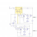
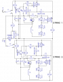
so all i add is R4, Q1, R3, and a Pfet? (DMP4065) is what i've been using.
i was letting some of the other stuff confuse me.
i think i understand this now.
could u recommend a NPN in smt package?
will these additional parts withstand transients as well as my other parts?
i've had major problems with transients before.
i'll be using bidirectional smaj26 tvs diode.
1 other issue is higher supply voltage. i would like customer to be able to power from 12 or 24 volts.
that's what the zeners are for.
will i need more zeners to protect these additional parts?
see if my schematic is right. it's late and i'm sleepy.
thanks for your patience and encouragement.
so all i add is R4, Q1, R3, and a Pfet? (DMP4065) is what i've been using.
i was letting some of the other stuff confuse me.
i think i understand this now.
could u recommend a NPN in smt package?
will these additional parts withstand transients as well as my other parts?
i've had major problems with transients before.
i'll be using bidirectional smaj26 tvs diode.
1 other issue is higher supply voltage. i would like customer to be able to power from 12 or 24 volts.
that's what the zeners are for.
will i need more zeners to protect these additional parts?
see if my schematic is right. it's late and i'm sleepy.
thanks for your patience and encouragement. View attachment 152202
The NPN selection is not at all critical. Standard, common parts like 2222, 3904 should definitely be fine, and I'm sure many others would do. I glanced at the datasheets for the first bunch of listings here, and all looked suitable:
I *think* the NPN will be fine without any special protection. The PFET probably needs Zener protection to make sure Gate-Source voltage never goes beyond +/-20V max limits.
It's past my bedtime, so no time to think through details of Zener gate protection, and it's possible my mind is drifting off on other issues as well!
it took most of the day but i got the circuit board laid out. my eyeballs are falling out.
it's tuff with single sided boards but only had to use 3 jumpers.
and it's confusing going back and forth from transistors to fets for connections.
let me know about zener protection and i'll be ready to order boards.
thanks
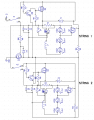
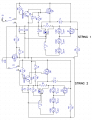
hope i don't get my head bit off again but i decided to try and think this through for myself.
i added zeners to limit voltage to Pfets.
would Z4 protect Q4 and Z5 protect Q5?
would R6 and R8 already there to pull the Pfet gate high also limit current to zener?
what do think of this CRUTSCHOW?
thanks ebeo
hope i don't get my head bit off again but i decided to try and think this through for myself.
i added zeners to limit voltage to Pfets.
would Z4 protect Q4 and Z5 protect Q5?
would R6 and R8 already there to pull the Pfet gate high also limit current to zener?
what do think of this CRUTSCHOW?
thanks ebeo View attachment 152287
Sorry, no luck with that one. You've got the Zener from gate to ground, but that doesn't solve the problem voltage scenario.
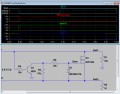
Your problem comes when the switch is in the top position, so both rails end up being powered (one via the MOSFET) meaning the MOSFET drain and source are both at 24V, but the gate is at ground. Since we want the drain and source voltages to remain 24V, we must use a Zener to keep the gate ABOVE ground potential. So, the Zener goes between gate and source. Unfortunately, in this placement you will need an extra resistor to limit current through the Zener anytime the higher voltages are present.
I only have a few minutes right now, and my LTSpice screenshots come together much more quickly, so this is all I can share right now:
Note that the Zener anode goes to gate and cathode goes to source/Rail2. The resistor must be between the Zener and the NPN.
I have trouble with them too. If it weren't for simulation software, I'd have zero confidence in my Zener opinions. As it is, I'm 99% sure what you've drawn perfectly captures what I was going for, and maybe 80% sure that my MOSFET and Zener circuit suggestions are a good solution for you.
I'd really appreciate it if some of the more experienced regulars here could double check me. I'd hate to have this all wrong and be wasting your time and energy. Hopefully we'll get a little confirmation and/or correction from someone else...
i think i understand this now and i have boards ready to order.
i wish crutschow would give us his blessing but i'm confident you have it right.
on the zeners, it seems they will limit voltage going to LEDs??? is that right?
what if i used 15 volt zeners?
or do they make fets that can withstand 30 volts?
where do i find simulation software like you have?
if this works, i'll have 2 heroes here... you and cruts.
thanks
I and ebeowulf17, among others on these forums, use LTspice, a free download from Linear Technology/Analog Devices.
It has a somewhat steep learning curve, but there are good tutorials and may circuit examples to help you learn. It's well worth the effort if you do any circuit design and want to better understand circuits.
The simulator does not always perfectly simulate the results of a real circuit but, chances are, if the simulated circuit doesn't give you the results you want, then the real circuit won't either.
Many times I've seen posts asking whether the "funny" results they are getting with the simulator is due to a bug in the simulator, but in almost all cases it's a bug in the design.
i think i understand this now and i have boards ready to order.
i wish crutschow would give us his blessing but i'm confident you have it right.
on the zeners, it seems they will limit voltage going to LEDs??? is that right?
what if i used 15 volt zeners?
or do they make fets that can withstand 30 volts?
where do i find simulation software like you have?
if this works, i'll have 2 heroes here... you and cruts.
thanks
The Zener shouldn't effect LED voltage, only gate voltage.
I don't see any problem with 15 volt Zeners. I hadn't looked at what you were using before, but 15 is what I imagined using here.
I don't know if there are FETs that can withstand higher gate-source voltages, but if so they'd be the exception. Most of what I've seen had a Vgs-max of 20 or less. I wouldn't go looking for different FETs if I were you.
Like crutschow said, LTSpice is what I use. It can be difficult learning new aspects of it at times, but it's amazingly powerful and useful. There are tons of experienced users on this forum, and many applications have already been discussed in depth, so usually I find the help I need in existing threads here, but occasionally I have to post a new question. Either way, plenty of help to be had.
these may be used on marine or automotive applications where voltage could go up to 14 volts from the charging system.
someone said i must use zeners higher than the highest supply voltage or it would turn on some of the fets when they should be off.
is that right?
my original circuit could run from 12 or 24 volts.
i guess 24 volts is out of question with this circuit?
thanks
This mystereous "someone" is wrong.
The zeners conduct at their rated voltage to limit the gate-source voltage when on, so yes, they will turn on at any voltage above their rated, which is their purpose.
If you select them for a voltage higher than the supply voltage than how can they provide any protection?
If you are bringing "someone" else into the discussion on this forum, please state who that is.
I'm glad you fielded that one! I hadn't looked at the other Zener arrangements at all yet, and I must confess I do still get myself turned around pretty often with both Zeners and MOSFETs, not to mention the combination of the two. I would've had to sim it to be sure. Thanks!
didn't mean to offend anyone.
he is on another site that helps people the same way as here.
says he is a circuit designer for a major custom electronics manufacturing firm.
i don't know enough to argue either way...i'm just trying to learn and understand.
i thought as long as the zener conducts below what the fet can handle, is all that's important???
i should have stated this first.
supply voltage could go up to 14.5V when alternator is charging.
my fets are rated at 20V maxGS so i thought 15V zeners would work?
if i'm wrong, please tell me.
is 26V supply impossible with this circuit?
thanks
I wish I could fathom quite what it is you are trying to do here. If you want to high side switch alternate led strings with ccs drivers you are making life very hard for yourself. The cost of gate protected big mosfets is not high. You can also protect them with a pair of back to back 10v zeners from G to S to suit all occasions P or N. To handle your transients with ease go for VDS max of 60V or more. That said, what is the relay for if not to switch between led drivers? Its carrying the full load current through its contacts already! So all you need is a way to control Q1,Q2 or better still buy a 4 pole relay and get rid of them. Q3s function is baffling. The over voltage and over current protection needs some thinking about and only needs to be implemented once. Why the costly extravagance, opulence even? Sorry to be so harsh. What about switching the ccs between the strings?
I wish I could fathom quite what it is you are trying to do here. If you want to high side switch alternate led strings with ccs drivers you are making life very hard for yourself. The cost of gate protected big mosfets is not high. You can also protect them with a pair of back to back 10v zeners from G to S to suit all occasions P or N. To handle your transients with ease go for VDS max of 60V or more. That said, what is the relay for if not to switch between led drivers? Its carrying the full load current through its contacts already! So all you need is a way to control Q1,Q2 or better still buy a 4 pole relay and get rid of them. Q3s function is baffling. The over voltage and over current protection needs some thinking about and only needs to be implemented once. Why the costly extravagance, opulence even? Sorry to be so harsh. What about switching the ccs between the strings?
i am electronically illiterate. i came here to get advice.
this is a light to be used on boats.
power can come from 12v starting battery or 24v trolling motor batteries.
k1 and k2 are spdt switches, center off.
Q3 is reverse polarity protection.
goal is to turn on 6 different combinations of LEDs.
23
123
2356
12356
23456
123456
with the help of crutschow, the original circuit works as desired.
the latest version is to replace diodes with Pfets Q4 and Q5 to lower overhead voltage requirement.
i will consider 60v fets or anything to reach my goal of lowering overhead required.
if that eliminates the need for zeners, it would be simpler.
and would it allow circuit to be powered by 12 or 24volts?
all the higher voltage fets have much higher ON resistance. doesn't that defeat the purpose?
what do you think cruts and ebeo?
thanks
I'm out of my depth here. Protecting a 20V gate from 24V with a 15V Zener is reasonably straightforward - I have to check myself a lot, but I can get though it. Dealing with "transients" of unknown nature, power, and duration leaves me very uncertain. I also have no previous experience with any of the specialized MOSFETs that DECELL referred to. I wouldn't be surprised if things can be simplified, but it's certainly beyond my expertise to do so.
So far, each post I've seen in this project represented incremental changes - dealing with one small issue at a time. The resulting schematic has grown quite a bit from the original question. It's quite possible that this project could be simplified now that a more complete set of user requirements and better sense of scale is known.
If you're seriously interested in more fundamental changes, one possibility would be to use "progressive" DPDT switches in place of your current switches. I'd have to sketch it to be totally sure I've got it right, but I'm pretty sure we can eliminate Q1, Q4, and associated Zeners, NPNs etc. by using a DPDT switch in place of K1 (and corresponding savings on the bottom circuit.) If you're interested, I'll get you some links for the kind of switch I mean and sketch up the modified circuit... no promises on how soon I could do that, but probably in the next few days anyway.

 Facebook
 Google
 GitHub
 Linkedin