
Hello,
I have been working on my project for quite a time on controlling the speed of a 220V, 60Hz, 0.35 induction motor (domestic fan), I use Arduino to generate 60Hz with a switching frequency of 10KHz, when I try my circuit with a 20V motor, It works well and I can even vary the frequency.
but, once I connect to 220V the MOSFETs suddenly burn (explode) and the gate driver burns too. I came to understand that I don't have much knowledge of what is going on back there.
components used:
OPTO-ISOLATOR - 4N35
MOSFET -IRF830
GATE DRIVER - IR2113
BOOTSTRAP CAP (MLCC) - 47uF
BOOTSTRAP DIODE - SCHOTTKY DIODE (400V)
I have tried to achieve deadband too but still, the same issue. I have converted AC to DC using a bridge rectifier, inductor (15mH, 4A), and DC link, (400V, 2200uF), then I fed this to my inverter,
if I miss any details or the knowledge, I would appreciate it, Thank you.
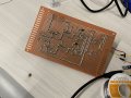
here is my attached inverter circuit design.
I have been working on my project for quite a time on controlling the speed of a 220V, 60Hz, 0.35 induction motor (domestic fan), I use Arduino to generate 60Hz with a switching frequency of 10KHz, when I try my circuit with a 20V motor, It works well and I can even vary the frequency.
but, once I connect to 220V the MOSFETs suddenly burn (explode) and the gate driver burns too. I came to understand that I don't have much knowledge of what is going on back there.
components used:
OPTO-ISOLATOR - 4N35
MOSFET -IRF830
GATE DRIVER - IR2113
BOOTSTRAP CAP (MLCC) - 47uF
BOOTSTRAP DIODE - SCHOTTKY DIODE (400V)
I have tried to achieve deadband too but still, the same issue. I have converted AC to DC using a bridge rectifier, inductor (15mH, 4A), and DC link, (400V, 2200uF), then I fed this to my inverter,
if I miss any details or the knowledge, I would appreciate it, Thank you.
here is my attached inverter circuit design.
Attachments
-
 3.8 MB Views: 64
 -
 3.6 MB Views: 66


